


Proving Tanks
Proving tanks shall be provided with drain valves at the bottom part; they should be designed with a top neck and may be designed with a bottom neck. The requirements given in Standard Test Measure on the diameter of the neck of standard test measures apply equally to the diameter of the top and bottom necks of proving tanks.
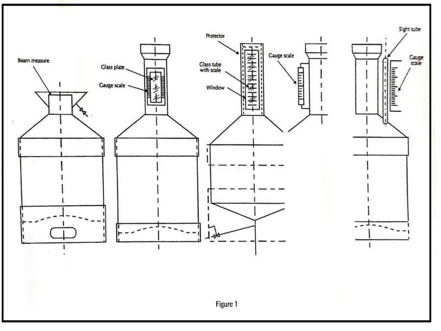
The top neck should be provided with glass plates or a separately fixed gauge glass(es), on which the scale marks corresponding to the nominal capacity and to variations of at least 1 % of the nominal capacity, in plus and in minus, are marked. Otherwise, the top neck part shall be fitted with a fixed and rustproof metal plate or a sliding plate capable of being sealed and on which the scale marks corresponding to its nominal capacity and to the volumes below and above the nominal capacity, are marked.
The bottom neck should be provided with glass plates or a separately fixed gauge glass(es) similar to the top neck, with scale marks corresponding to volumes of only 0.5 % in plus or in minus of the nominal capacity.
The diameter of the gauge glasses connected to the top and bottom necks shall be large enough to ensure that capillary or meniscus effects do not introduce additional uncertainties such that the maximum permissible errors (±½ 000 of the nominal capacity as given in clause 2.2.2.2 of OIML R 120) are exceeded.
It shall be ensured that the liquids are easily delivered to and from the proving tanks and that no pockets, dents or crevices capable of trapping the liquid, air or vapor are present.
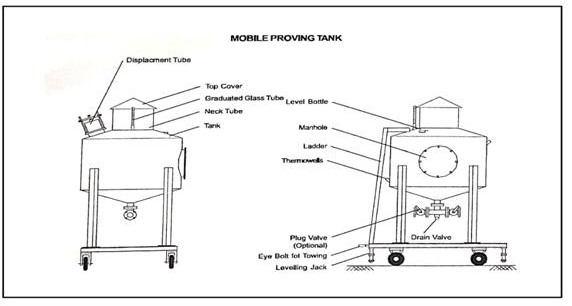
Examples of different designs of a proving tank are shown in Figure 2.
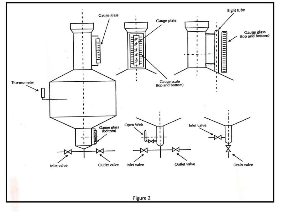
The proving tank shall be provided with means for measuring the temperature of the liquid it contains. When thermometer wells are used for determining the temperature of the test liquid in the proving tank, the minimum recommended number of thermometer wells is given in Table 2.
TABLE 2
| Nominal capacity of a proving tank | up to 500 L | more than 500 L up to 2 000 | more than 2000 L |
| Minimum number of thermometer wells | 1 | 2 | 3 |
The thermometer well shall be deep enough to enable the correct immersion of a thermometer and shall consist of a metal socket with good heat conductivity having one end closed; it shall be inclined so that liquid can be added to the well if desired. The thermometer wells shall be installed with such an immersion that the ambient temperature outside the proving tank will not affect the thermometer.
When the installation of two or three thermometer wells is recommended, these shall be installed in accordance with the following location conditions:
a. In the upper and lower half of the main body, or in the upper and lower third and near the center of the main body of the proving tank, and
b. At two or three points, equally spaced around the circumference of the proving tank.
Where proving tanks are mounted on a truck or trailer, means shall be provided to secure and maintain them in a level position, during testing and use.
For testing certain types of measuring systems (for example, those for the recep tion of milk), it may be easier to use proving tanks of the brim measure type.
MATERIALS OF CONSTRUCTION
Body: Carbon steel (internally epicoated) Stainless Steel
Displacement Tube: Carbon steel (zinc plated / yellow passivated) Stainless Steel
Graduated Glass: Borosil glass
Thermowells: Carbon steel
Drain Valve: Carbon Steel Stainless Steel
stamping and sealing arrangement
The image shows a diagram of a stamping and sealing arrangement, with a focus on the adjusting device and the manhole cover. The diagram illustrates how a sealing wire is used with a seal for security.
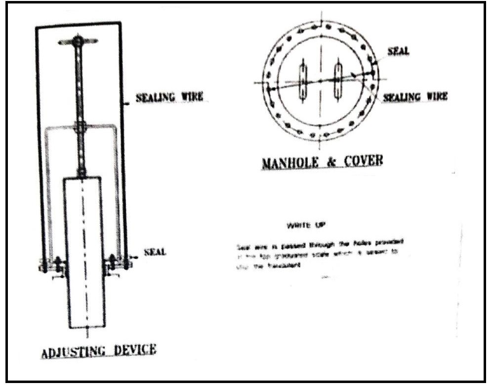
The sealing is done by a seal wire is passed through the holes provided at the top graduated scale which is sealed to stop the fraudulent practices. A typical schematic diagram of sealing provision to prevent the fraudulent practices of the model is given above.
Fixed Proving Tank
The sealing arrangement of a fixed proving tank is designed to ensure permanent leak-proof integrity and measurement stability. All openings such as inlet and outlet pipes, manholes, air vents, drain points, and calibration fittings are sealed using approved gaskets, sealing compounds, or metal-to-metal joints. These seals prevent leakage, evaporation, and air entry, which could otherwise affect the calibrated volume of the tank.
Since the tank is installed at a fixed location, the sealing arrangement is rigid and long-lasting. Once sealed, the joints are not frequently disturbed, ensuring consistent performance over time. Proper sealing also allows the tank to comply with legal metrology and calibration standards, ensuring accuracy and reliability during repeated proving operations.
Mobile Proving Tank
The sealing arrangement of a mobile proving tank is specially designed to withstand frequent movement and transportation. All flanged joints, valves, manholes, and connections are fitted with high-quality, flexible gaskets and sealing materials that can absorb vibration and mechanical stress during transit. This ensures the tank remains leak-proof even under changing operational conditions.
Additional attention is given to ensuring that seals remain intact during loading, unloading, and site operations. Locking arrangements and secure fittings are often used to prevent loosening of sealed components. Effective sealing ensures that the calibrated volume of the mobile proving tank is maintained, allowing accurate and reliable proving at multiple locations.
Looking For Advice?
WORKING PRINCIPLE
Proving Tanks are designed and manufactured in accordance with Indian Standard IS. 2341 and Manual of Weights & Measures.
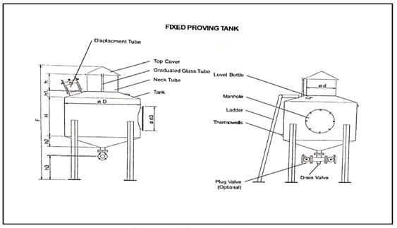
A Proving Tank consists of a cylindrical shell welded between two conical ends, which ensures smooth flow of liquid while draining the tank. Fitted to the bottom cone is a T-joint (where inlet and outlet isolation valves can be fitted) and a drain valve to assist in filling and draining of the tank. The top cone is fitted with a neck tube, having a conical top cover to prevent ingress of dirt in the tank.
A graduated glass tube is externally fitted to the neck tube, which indicates the liquid level in the neck tube. Graduations on the tube correspond to the volume per unit height of the neck tube
The cylindrical shell has a manhole fitted with a bolted cases, which can be opened for internal inspection, painting, etc. A displacement tube arrangement is provided on the top cone to adjust the internal tank volume with the tank capacity snack on the graduated glass tube. For accurate adjustment of tank level, rest pad is fixed to the top cone for keeping level bottles. The body also has two thermowells capable of accepting mercury in steel type thermometers.
A baffle plate provided at the point of liquid entry in the bottom cone, prevents swirl or vortex formation and related trapping of air in the liquid. The entire lank is erected on a sturdy steel channel frame, which can be either grouted (for a fixed Proving Tank) or boiled to a movable trolley Is case of a mobile Proving Tank). In the latter case, the trolley comes with a tow bar and leveling screw jacks. The choice of a centrifugal pump with motor to fill or drain the liquid is optional, both for fixed or mobile tanks.
OPERATION MANUAL
Proving Tanks are designed and manufactured in accordance with Indian Standard IS.2341 and Manual of Weights & Measures.
A Proving Tank consists of a cylindrical shell welded between two conical ends, which ensures smooth flow of liquid while draining the tank. Fitted to the bottom cone is a T-joint (where inlet and outlet isolation valves can be fitted) and a drain valve to assist in filling and draining of the tank. The top cone is fitted with a neck tube, having a conical top cover to prevent ingress of dirt in the tank.
A graduated glass tube is externally fitted to the neck tube, which indicates the liquid level in the neck tube. Graduations on the tube correspond to the volume per unit height of the neck tube.
The cylindrical shell has a manhole fitted with a bolted cases, which can be opened for internal inspection, painting, etc. A displacement tube arrangement is provided on the top cone to adjust the internal tank volume with the tank capacity snack on the graduated glass tube. For accurate adjustment of tank level, rest pad is fixed to the top cone for keeping lev el bottles. The body also has two ther m owells capable of accepting mercury in steel type thermometers.
A baffle plate provided at the point of liquid entry in the bottom cone, prevents swirl or vortex formation and related trapping of air in the liquid. The entire lank is erected on a sturdy steel channel frame, which can be either grouted (for a fixed Proving Tank) or boiled to a movable tr olley Is case of a mobile Proving Tank). In the latter case, the trolley comes with a tow bar and leveling screw jacks. The choice of a centrifugal pump with motor to fill or drain the liquid is optional, both for fixed or mobile tanks.
APPLICATIONS
- Calibration of field mounted liquid flow meters or master meters
- Vehicle tank calibration
- Calibration of bulk measures
TEST PROCEDURE FOLLOWED BY MANUFACTURER
The test procedures described in Clauses 6 to 12 may be used for the testing of the following typical measuring systems:
Clause 6 – Meter On Its Own Or Fitted With Ancillary Devices
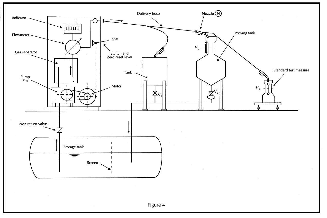
Clause 7 – Fuel Dispenser
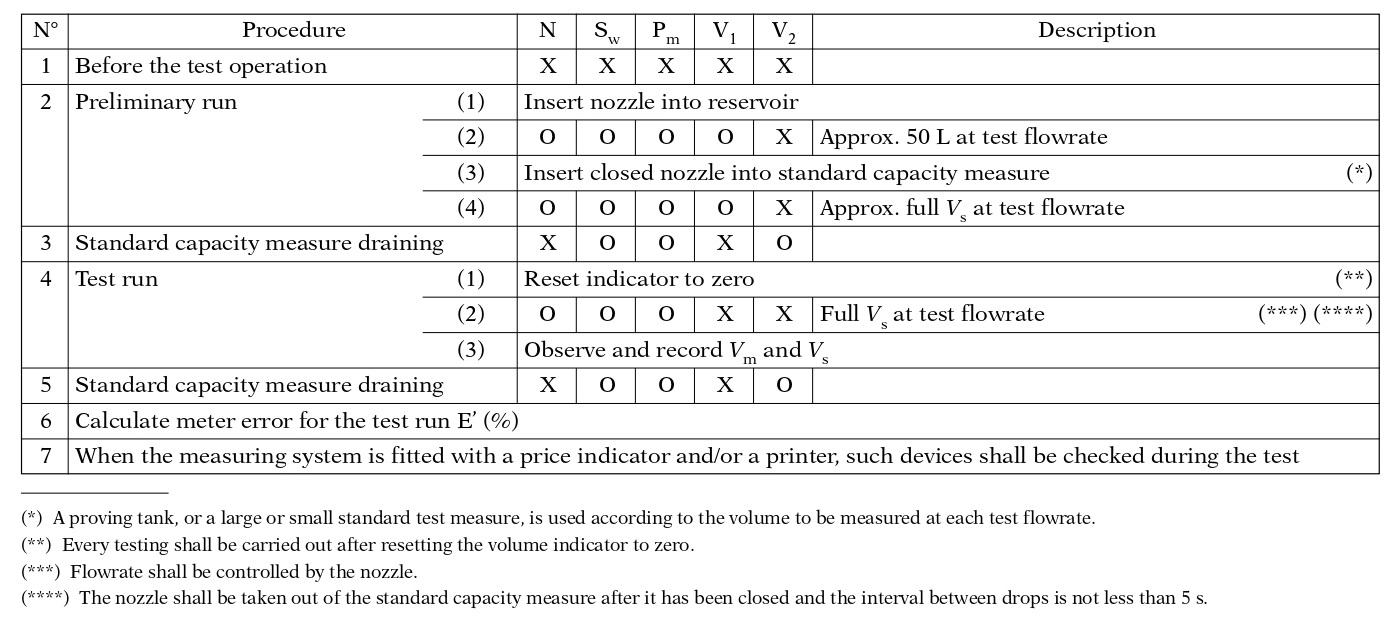
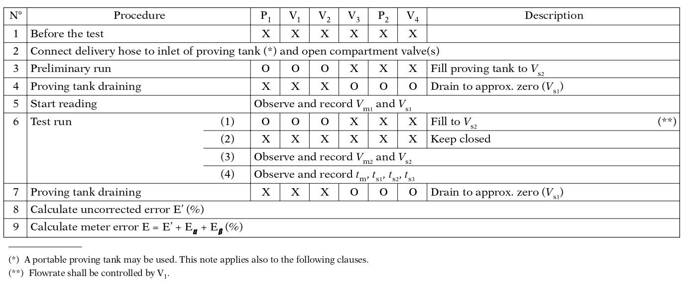
Test procedure for a fuel dispenser (Figure 4)
Clause 8 – Measuring System On A Road Tanker
Test procedure for a measuring system on a road tanker
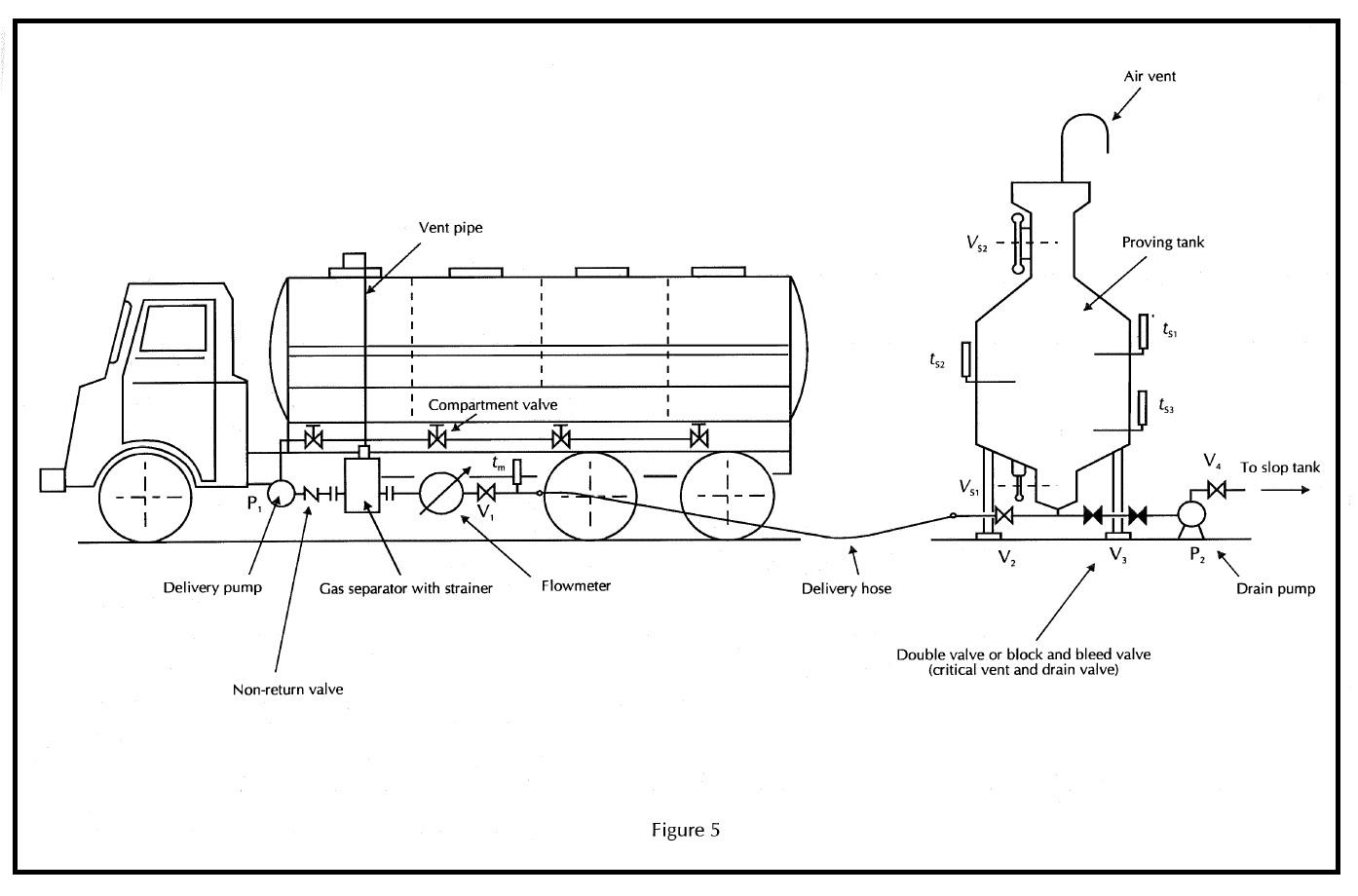
Clause 8.1 – In The Case Of A Road Tanker With Delivery Pump (Figure 5)
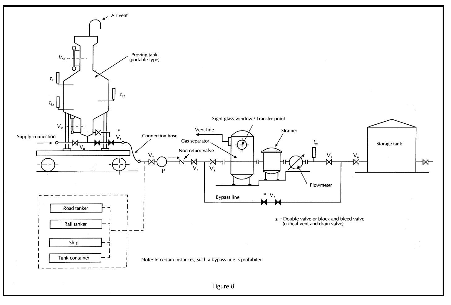
Clause 9 – Measuring System For The Unloading Of Road And Rail Tankers, Ships' Tanks And Tank Containers
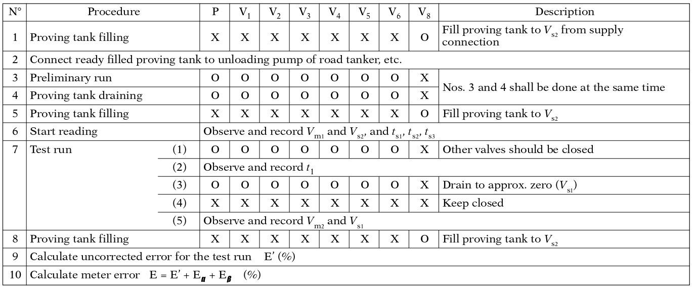
Note: This method should be applied, for example, when the test is impossible during an unloading operation.
Clause 9.2 – Test Run Being Carried Out Without Unloading Operation (Figure 8)
Clause 10 – Measuring System For The Loading Of Road And Rail Tankers, Ships' Tanks And Tank Containers
Clause 11 – Measuring System Fitted Into A Pipeline
Clause 12 – Measuring System For Milk
It should be noted that many other acceptable methods exist, which may be described in OIML Recommendations or ISO Standards. The examples given illustrate the range of possible methods. The sole criterion for acceptability is compliance with the metrological requirements of this Recommendation, ensuring the integrity of testing.