
M/S. Girish Chandra Ghosh & G.G.S
FORMERLY M/S GIRISH CHANDRA GHOSH ESTD. 1874
Govt. Approved License Manufacturer / Repairer & DealerGovt. Approved Calibrator of Storage Tank of Petroleum, Chemical, Oil, Other Liquid Storage Tanks, Manufacturer of Weighing Machines and Complete Weighing Solution, Peg Measure. Leading Storage Tank Calibrator & Surveyor, N.D.T Inspection work, Inspection Survey & P.I Diagram in
India & Abroad
Methodology used (International Standard : OIML Approved)
(India is a member country of OIML)
ISO 7507-1: 2003 Petroleum and liquid petroleum products - Calibration of vertical cylindrical tanks - Part 1: Strapping method
ISO 7507-2: 2005 Petroleum and liquid petroleum products - Calibration of vertical cylindrical tanks - Part 3: Optical-triangulation method
ISO 7507-3: 2006 Petroleum and liquid petroleum products - Calibration of vertical cylindrical tanks - Part 2: Optical-reference-line method
ISO 7507-4: 2010 Petroleum and liquid petroleum products - Calibration of vertical cylindrical tanks - Part 4: Internal electro-optical distance-ranging method
ISO 7507-5: 2000 Petroleum and liquid petroleum products - Calibration of vertical cylindrical tanks - Part 5: External electro-optical distance-ranging method
FOR VERTICAL STORAGE TANK
2007-1974: Method for Calibration of Vertical oil storage tanks
2008-1961:Method for computation of capacity tables of vertical oil storage tanks
Weights and Measure (Legal Metrology Department) Rules – Ninth A Schedule, Part No. II & III of the S.W.M. (General) Rules, 2011
FOR HORIZONTAL STORAGE TANK
2009-1975: Method for Calibration Horizontal and tilted oil storage tanks
2166-1963: Method for computerisation of capacity tables for horizontal and tiled oil storage tank
STATUTORY OBLIGATION FOR CALIBRATION
As per the provision of section 27of the standard weights and < General> measure rule 2011 no weights and measure shall be sold or offered possessed for sale use of kept for use in any transaction or protection unless it has been verified & stamp and as provided in State Enforcement Rule 2011 framed under the Legal Metrology act 2009. The storage tank including vats used or intended to be used in any Transaction or tor protection must be revivified or recalibrated and stamp at least once in 5 years the definition of the word the Transaction defined in 2 < u> of the standard Legal Metrology act 2009 under which the said act has been enacted which runs as follows :-
- any contract for Sale, Purchase, Exchange or any other purpose.
- any assessment of Royalty, Toll or other dues.
- any assessment of work done, wages dues or service rendered, their Storage tank can't be excluded from the purview of the above said Act & Rules.
For ISO quality certification of Calibration of Storage Tank is essential accurately required by ISO official
- To meet Central Excise / State Excise & custom Duty obligation in view of the aforesaid - it is essential to get storage tank calibrated by owners and to get rid of any legal action as provided in the said Act.
- Fines & seizures for noncompliance.

NOTE: In India storage tank calibrated maintaining legal metrology act and rules only as it is prescribed. Other method beside it can be done outside India. All methods subject to approval of Legal Metrology Rule 2010.
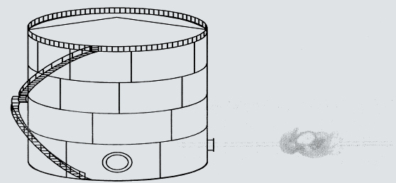
PROCEDURE OF VERTICAL STORAGE TANK CALIBRATION
STEPS FOR CALIBRATION
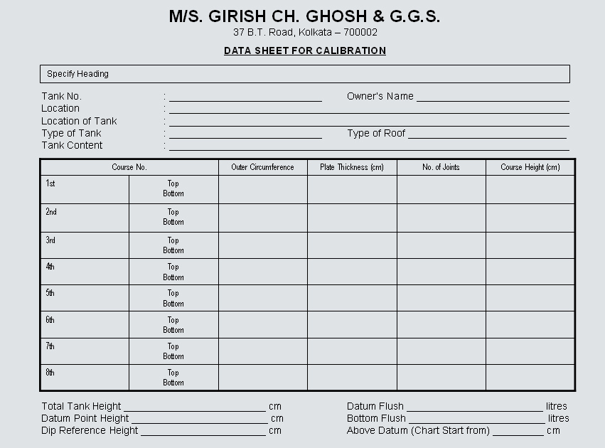
1. Strapping (Linear & Non Linear measurement)
- Circumference measurement of each course at least 2 per course
- Taking of course height and total tank height
- Plate thickness detection
- No. of joints and its step-over correction
- Detection of DIP reference height
- Safe height detection
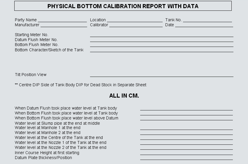
2. Bottom Calibration (in side tank work)
- Fitting water flow meter with water connection and taking reading opening & closing for datum flush
- Taking datum height
- Water level at various places in side the tank as when required in calibration process
- Deadwood correction factor (+ factor and – factor) taking into consideration
3. For Floating Roof
- Height of the deck
- Weight of the roof
- Density correction
- Inaccurate zone detection
4. Preparation of computerised calibration chart with CD and drawing with detail report as required
5. Approval and certification from Govt. Statutory Body
SAVE OIL. BETTER & SMOOTH OPERATION, STOP WASTAGE & PILFERAGE BY ACCURACY IN STORAGE TANK CALIBRATION
Indian Standard Specification for Vertical Storage Tank based on Indian Standard on Petroleum Measurements.
2007-1974: Method for Calibration of Vertical oil storage tanks
2008-1961: Method for computation of capacity tables of vertical oil storage tanks
Indian Standard Specification for Horizontal Storage Tank based on Indian Standard on Petroleum Measurements.
2009-1975: Method for Calibration Horizontal and tilted oil storage tanks tanks
2166-1963: Method for computerisation of capacity tables for horizontal and tiled oil storage tank
Weights and Measure (Legal Metrology Department) Rules – Ninth A Schedule, Part No. II & III of the S.W.M. (General) Rules, 1987
PLEASE NOTE
Items required for Storage Tank Calibration work
ARRANGEMENT
Govt. Statutory Fees & Inspector's Conveyance
FOR STRAPPING
Scraffolding:- For Linear/Non Linear Measurement & Ultrasonic Thickness Test Clean surroundings at tank site etc.
FOR PHYSICAL BOTTOM CALIBRATION
- Water/Product connection with hose
- Pipe/Flunge/Fittings/Reducer arrangement for Fitting and Fixation of water/flow meter
- Manhole opening should be there
- Clean and clear bottom
- Lighting arrangement if required
- Inlet & Outlet should be closed properly
FLOATING ROOF TANK FOR ROOF FLOATATION
- Water connection with hose
- Position to fit water meter with connection fittings arrangement for it from your part
- Tank should be Box up and Manhole fitted
- Roof at working height (i.e. lower leg position)
- Staying facilities if required during the time of floatation work
DEADWOOD CALCULATION SHEET
Manhole 1Range From To Inner Dia – Depth – Total Vol. – Per cm. Vol. – |
Manhole 2Range From To Inner Dia – Depth – Total Vol. – Per cm. Vol. – |
Nozzle 1Range From To Inner Dia – Depth – Total Vol. – Per cm. Vol. – |
Nozzle 2Range From To Inner Dia – Depth – Total Vol. – Per cm. Vol. – |
Roof SupportRange From To Inner Dia – Depth – Total Vol. – Per cm. Vol. – |
(Any type of pipe)Range From To Inner Dia – Depth – Total Vol. – Per cm. Vol. – |
CoilRange From To Inner Dia – Depth – Total Vol. – Per cm. Vol. – |
LegsRange From To Inner Dia – Depth – Total Vol. – Per cm. Vol. – |
METHODS FOR CALIBRATION OF VERTICAL STORAGE TANKS GENERAL SECTION
A. SCOPE:
This part prescribes the methods for calibration of vertical storage tanks with or without a tilt used for bulk storage of liquids of atmospheric pressure or under low or high pressure with or without heating or cooling mounted aboveground or underground or on ships or barges either by strapping method (SM) by internal ultrasonic distance ranging method (IUDRM) or by internal electro – optical distance ranging method (IEODRM).
B. DEFINATIONS:
(1) Storage Tank (thereafter referred to as ‘tank’) – Specified modes of the inclination including a vat exceeding on kilolitre in capacity used for bulk storage of liquids or liquefied gases at atmospheric pressure or under low or high pressure with or without heading or cooling mounted aboveground or underground or on ships or barges together with its necessary supports, manholes, piping valves, gauges, meters etc, which shall be calibrated as a capacity measure.
(2) Vertical Tank – A tank in the shape of a right circular or elliptical cylinder or of a frustum of a cone or of a rectangular parallelepiped, the axis of geometric symmetry of which is vertical to the base of mounting with or without a tilt.
(3) Floating Roof Tank – A tank in which the roof floats freely on the surface of the liquid contents except at low levels when the mass of the roof is taken through its supports by the tank bottom.
(4) Datum Plate – A horizontal metal plate located along the vertical axis descending from the dipping reference point, providing a fixed contact surface from which liquid dip measurements are made.
(5) Dip Hatch – An opening in the top of a tank through which dipping, ullaging or sampling operations are carried out.
(6) DIP Pipe – A perforated metal pipe fitted below the dip hatch which projects downwards, ending near the bottom of the tank, directly above the dipping datum point and acts as a guide for the dip weight, particularly, when obstructions have to be avoided and it is obligatory in the case of a floating roof tank.
(7) Dipping Datum Plate – A point of intersection of the vertical measurement axis with the upper surface of the datum plate which constitutes the origin or zero reference for the measurement of liquid dips.
(8) Dipping Reference Point – A point clearly marked on the dip hatch located along the vertical axis ascending from the dipping datum point to indicate the upper reference position to which ullage is measured.
(9) Overall Height – The vertical distance between the dipping reference point and the dipping datum point which shall be marked on the tank at the dip hatch.
(10) Dip – The vertical distance between the dipping datum point and the liquid level.
(11) Ullage – The vertical distance between the liquid level and dipping reference point.Note: the term ‘outage’ is synonymous.
(12) Equivalent Dip – A dip corresponding to a given ullage which is obtained by subtracting the observed ullage from the overall height.
(13) Course – One circumferential ring of plates in a tank.
(13) Course – One circumferential ring of plates in a tank.
(14) Step Over – A device of metallic or wooden frame holding two scribing points used in strapping for measuring the distance apart along the arc of two points on a tank shell where it is not possible to use a steel tape directly because of an intervening obstruction (e.g. a protruding fitting or an intruding dent). The difference between the apparent distance between two points on a tank shall as measured by a strapping tape passing over on obstruction and the true arc distance as measured by a step-over in termed as a ‘void’. If the apparent distance is greater than the true arc distance, the void is said to be ‘negative’. The corrected circumference is obtained by subtracting the algebraic sum of the voids from the measured circumference.
(15) Deadwood – Any tank fitting referred to as ‘positive’ when the capacity of the fitting adds to the effective capacity of the tank, or ‘negative’ when the capacity of the fitting subtracts from the effective capacity.
(16) Automatic Level Gauge – An instrument using mechanical and/or electronic devices intended to measure automatically the level of the liquid contained in a tank with respect to a fixed reference point.
(17) Open Capacity – The calculated capacity of a tank or part of a tank before any allowance has been made for deadwood.
(18) Capacity Table – A tabular representation often referred to as a tank table or a calibration table, showing the capacities of, or volumes in, a tank corresponding to various liquid levels measured from a stable reference point.
RECOMENDED RECORD FORM FOR MEASUREMENTS OF VERTICAL TANKS CLAUSE 5(1)
A. General Data …………………………………………………………………
Report No. …………………
Date ………………………
| 1. Tank No.: ………………… | 10. Angle or Tilt from Vertical: ………………………… |
| 2. Type of Tank Joints: Riveted/Lap-welded/Bun-welded | 11. Name of liquid intended to be contained: ……………… |
| 3. Nominal Tank Capacity: …………………… litres | 12. Temperature of Liquid required to be maintained in the tank if it is thermally insulated: …………… °c |
| 4. Type of Roof: Fixed/Floating/Hybrid/Variable Volume | 13. Density of liquid at the ambient or maintained temperature: …………………. Kg/m3 |
| 5. Mass of Floating Roof: ………………… kg | 14. Average ambient temperature during calibration: ………………. °c |
| 5. M6. Type of Bottom: Flat/Cone-up/Cone-down/with or without knuckle radius/Spherical segment/Hemispherical/ Semi-ellipsoidal segment | 14. Average ambient temperature during calibration: ………………. °c |
| 6. Type of Bottom: Flat/Cone-up/Cone-down/with or without knuckle radius/Spherical segment/Hemispherical/ Semi-ellipsoidal segment | 15. Whether equipped with automatic level gauge: Yes/No |
| 7. Height of Depth of Crown: …………………. mm | 16. Whether equipped with computerised liquid stock accounting systems: Yes/No |
| 8. Overall Height: ……………………… mm | 9. Height of Datum Plate: …………………….. mm |
B. Shell Circumferences or Diameters:
- 1st Course: …….. mm
- 2nd Course: …..... mm
- 3rd Course: …….. mm
- 4th Course: …….. mm
- 5th Course: …….. mm
- 6th Course: …….. mm
| No. | Description | Elevation. Top of Floor to Bottom of Connection mm |
| 1 | ||
| 2 | ||
| 3 |
C. Bottom Course Shell Connections:
| Course No. | Shell Plate Thickness (mm) | Width of Lap of Strap (mm) | Thickness of Strap (mm) | No. of Vertical Joints | Exposed Course Height (mm) | Inside Course Height (mm) |
| nth | ||||||
| 2nd | ||||||
| 1st |
D. Bottom Course Shell Connections:
| No. | Description | Size | Thickness of Strap (mm) | No. of Vertical Joints |
| nth | ||||
| 2nd | ||||
| 1st |
4. INTERRUPTED MEASUREMENTS:
(1) All tanks shall be calibrated in an empty condition and in gas-free state. All regulation covering entry into hazardous areas and explosive atmospheres shall be rigorously observed.
(2) All ladders shall be securely lashed in position before being used. When painters’ cradles or bo’suns’ chairs are used, any item of questionable calibration cannot be carried out without the use of staging, properly constructed steel tube or timbre scaffolding shall be worn by the operating personnel working above ground level.
(3) Measurement shall be taken only after the tank has been filled at least once at its present location with liquid to be stored to its working capacity or with water to its equivalent height, and such liquid or water has been held in the tank for at least 24 hours to allow for setting.
(4) All data and methods , whereby measurements are obtained, necessary for the preparation of tank capacity tables, shall be in accordance with sound engineering principles.
(5) When manufacturer’s drawings for the tank are available, all measurements shall be compared with those obtained from the drawings and measurements showing discrepancies grater than the tolerance specified in clause 7.
(6) In the case of tank mounted on ships or barges, all dip measurements shall be taken in a plane perpendicular to the even keel water line over minimum surface ripples.
(7) The strapping method shall be applied only to a tank in the shape of a cylinder or a conical frustum. The tanks of all other shapes shall be calibrated by any suitable internal or external measurement methods.
4. INTERRUPTED MEASUREMENTS:
If the calibration of a tank is required to be interrupted, it may be resumed with minimum delay, without repetition of work previously completed provided that:
(a) There is no major change in equipment and as far as possible, no change in personnel
(b) All records of work done are complete and legible; and
(c) Some hydrostatic head as before its maintained in the tank
5. DESCRIPTIVE DATA:
(1) Complete descriptive data shall be entered on the Tank Measurement Record Form being used. A schematic diagram of a typical fixed roof cylindrical tank of circular cross section is given in Fig. 55 and a recommended record form is shown in Table 50. (2) Supplemental sketches or notations each completed, identified dated and signed, shall form an important part of field data. These shall be made to indicate typical horizontal and vertical joints, number of plates per course, locations of courses at which thickness of plates changes, arrangement and sizes of pipes and manholes, dents and bulges in shell plates, direction of lean from vertical, method used in bypassing a large obstruction, such as clean-out box or insulation box located in the path of a circumferential measurement, location of tape path, location and elevation of possible datum plate and all other items of interest and value which will be encountered. (3) All measurements made by the calibration authority shall be recorded on site and shall not be subjected to subsequent correction.
6. DEGREE OF ACCURACY:
In order to obtain maximum obtainable accuracy in tank capacity tables, adjustments for effects of the following variables shall be incorporated in the tables:- (a) Expansion and contraction of steel tank shell due to liquid heads (b) Tilt from upright position, and (c) Tank bottoms that are irregular in shape Note: The degree of accuracy desired or required in the completed tank capacity table for a specific tank shall be the governing factor in determining the procedure to be followed.
7. EXPANSION AND CONTRACTION OF STEEL TANK SHELLS DUE TO LIQUID HEAD AND TEMPERATURE :
As the tank shells expand under liquid head contained therein, a liquid head correction shall be applied to the tank capacity table during normal service. The tanks are also affected by thermal changes, as are any measuring tapes used, such as strapping and dip tapes which are calibrated to be correct at the appropriate reference temperature, e.g. 20°c. if the tank capacity table is required.
8. TOLERANCES:
Measurements shall be read to the nearest 1 mm and within tolerance given in Table 51, when readings are taken at the same point.
TABLE 51 – SPECIFIED TOLERANCES
| Tank Circumference, C (m) | Tolerance (mm) |
| C < 25 | ± 2 |
| 25 < C < 50 | ± 4 |
| 50 < C < 100 | ± 6 |
| 100 < C < 200 | ± 8 |
| 200 < C | ± 10 |
At a reference tank shell temperature offer than the reference temperature of the tape, the linear measurements shall be adjusted by temperature correction.
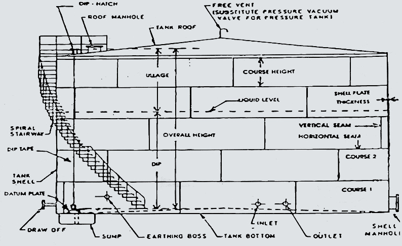
FIG. 56 – A SCHEMATIC DIAGRAM OF TYPICAL FIXED ROOF CYLINDRICAL TANK
SECTION 1 – CALIBRATION BY STRAPPING METHOD
9. GENERAL
(1) The method is based on the measurement of external circumference which are subsequently corrected to yield the true internal circumference.
(2) The stipulated number external circumference measurements together with subsidiary deviation of the tape from the true circular path shall be obtained as described under clause 11.
(3) An internal diameter may be measured at approximately, the same height as that at which a circumferential measurement is desired.
(4) If may be necessary in practice to refer all tank dips to a datum point other than the datum point used for the purpose of tank calibration. If so, the difference in level between these datum points shall be determined either by normal surveying methods or by other suitable means.
10. EQUIPMENT
(1) Steel Tapes – Shall comply with the specifications under Part VII of the Sixth Schedule. The tape shall be
greased well before use.
(2) Spring Balance – Reading up to 10 kg. with 0.1 kg. graduations is necessary for measuring the tension
applied to the tape. It is preferable to have two balances. Spring balance shall comply with specifications
given under Part IV of the Seventh Schedule – Heading A.
(3) Step Over – This is used to correct deviation
of the tape from its normal circular path, namely passing over fittings or joints between plates.
(4) Dip
Tape and Dip Weight – Complying with the specifications given under Part IX of the Sixth Schedule.
(5)
Loops and Cords – One a more metal loops which can slide freely on the tape and to which are attached two
cords, each of sufficient length to reach from the top of the tanks to ground. The tape is positioned and its
tension evenly distributed by passing these loops around the tank.
(6) Accessory Equipment – Rope, Hooks,
Safety Belts, Ladders, Painters’ Cradles etc.
(7) Miscellaneous Equipment – Steel Rule, Spirit Level, Awl
and Scriber, Marking Crayon, Plumb Line, Dumpy Level, Positive Displacement Bulk Meter, Water Meters, Proving
Measures etc.
11. CIRCUMFERENCE MEASUREMENTS
(A) STRAPPING LEVELS
Circumferences shall be measured by a minimum of two strapping per course at the following levels:(a) For riveted tanks -
(1) At 7 per cent to 10 per cent of the height of exposed portion of each course above the level of the upper edge of each horizontal overlap between courses (see A of Fig. 57(a)), and (2) At 7 per cent to 10 per cent of the height of edge of each horizontal overlap between courses and below the level of the lowest part of the top angle iron of the rank (see B of Fig 57(a)).
(b) For welded tanks –
(1) Two levels (see A and B of Fig. 57(b) for Lap-welded tanks and of Fig. 57(c) for butt-welded tanks), the upper and the lower levels, at the top and bottom of courses shall be 20 per cent of the height of the exposed portion of the respective courses away from the angle iron seams. (2) Circumferential tape paths, having been located at elevations as under 11(A)(a) above shall be examined for obstructions and type of vertical joints. Projections of dirt and scale shall be removed along each path. (3) Occasionally, some feature of contraction such as a manhole or insulation box, may make it impracticable to use a circumference evaluation at the prescribed location. If the obstruction can be spanned by a step-over, then the circumference shall be measured at the prescribed elevation, using a a suitable method given under 11(C)(2)(d). If the obstruction cannot be conveniently spanned by a step-over, then a substitute path located nearer to the centre of the course may be chosen. The strapping record shall include the location of the substitute path and the reason for the departure. The type and characteristics of vertical joints shall be determined by close examination in order to establish the method of measurement and equipment required. If the tape is not in close contact with surface of the tank throughout its whole path owing to the vertical joints a step-over shall be applied so that a correction may be calculated to adjust the gross difference for this effect.
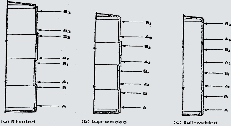
FIG. 57 – LOCATIONS OF STRAPPING LEVELS FOR DIFFERENT TYPES OF TANK JOINTS
(B) STRAPPING PROCEDURE
(1) The tank shall be strapped by either of the methods described under (2) and (3) below. In either case a
tension of 4.5 ±0.5 kg shall be applied to the tape and if necessary, transmitted throughout its length by
suitable means, namely, by means of metal loops sliding freely on the tape, the loops being passed around the
tank by operators with the aid of light chain or cords. The tape path shall be parallel with circumferential
seams of the tank.
(2) If the tape to be used is not long enough to encircle the tank completely, then after the level of the
tape
path has been chosen, fine lines shall be scribed perpendicular to this path to allow the circumference to be
measured in sections. The scribed lines shall be drawn in the middle circumferential third of any plate at
such
distances as will ensure that the whole of the length of the tape used is under the observation of one or
other
of the operators. Subject to the conditions under 11(A)(b)(3) and 11(A)(b)(4), the external circumference of
the
tank is then the sum of the lengths between the scribed lines.
(3) If the tape to be used can encircle the tank completely, then after the level of the tape path has been
chosen, the tape is passed around the circumference and held so that the first graduated centimeter lies with
the middle circumferential third of any plate. The other end of the tape shall be brought alongside. The
tension
is then applied through the spong balance and transmitted throughout the length of the tape.
(4) After a a circumference has been measured (see (9) above), the tape shall be shifted a little around the
tank, brought to level and tension as above, and the reading repeated. The final reading shall be the
arithmetic
average of the readings.
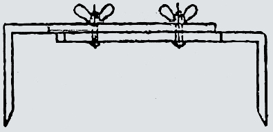
C. STEP-OVERS
(1) Principles
If the tape crosses obstructions, such as projections, deformities, fittings or lapped joints, it well deviate
from a true circular path and an erroneous circumferential measurement will result. In order to avoid such
errors a ‘step-over’ is used to measure the correction to be applied for such obstructions, a suitable design
of
which is given in Fig. 58.
(2) User of Step-Over
(a) For obstructions, the strapping tape shall be stretched as if in measurement of a circumference on the
tank
which is being calibrated, but not within 300 mm of any horizontal seam. The scribing points shall then be
applied to the tape near the middle of a plate where the tape is fully in contact with the tank surface. The
length between the points, as measured on the curved tape is then read off as closely as possible, fractions
of
tape deviations being estimated. The reading shall be repeated on a minimum of two and maximum of four plates
equally spaced around the circumference, and the average of the results taken, as the step-over will vary with
tank diameter and the course concerned since they are made on surface differently curved.
(b) With, the tape still in position and under the tension used in strapping, the step-over shall be applied
to the tape on either side of each obstruction lying on the tape path, and readings shall be taken of the
lengths of tapes included between the scribing points. All step-over readings shall be recorded for subsequent
use in calculation.
(c) Care shall be taken in placing the instrument in a truly level position at each obstruction to avoid
distortions in circumferential path, in the case of a step-over of relatively long space, the use of a spirit
level is recommended as an aid in determining its correct position before scribed marks are stuck off on the
places.
(d) When the butt-strap or lap joint, or tank shell, include rivets or other features which exert uneven
effects on the resultant void between tape and tank from joint to joint, then a step-over will be required.
The span of the instrument should be measured prior to use in accordance with 11(C)(2)(a) and above. The two
legs should be separated by a distance sufficient to spar each void between tape and shell encountered. The
legs shall be of sufficient length to prevent contact between the inter-connecting member and the tank plate
or obstruction. Stretch the tape over the joints and place the step-over in position at each location of void
between tape and shell, completely spanning the void so that the scribing points, with the tape maintained in
proper position and tension, should be estimated to the nearest 0.5 mm. At each step-over location, therefore,
the difference between the length of tape encompassed by the scribing points and the known span of the
instruments is the effect of the void, at that point, on the circumference as measured. The algebraic sum of
such differences in an given path, subtracted from the measured circumference, will give the corrected
circumference.
12. SHELL PLATE THICKNESS
(1) Where the type construction leaves the plate edges exposed, minimum of four thickness measurements shall
be
made on each course of points approximately equally spaced about the circumference. The arithmetical average
of
the measurements for each course shall be recorded; all thickness measurements, property identified, shall be
noted on a supplemental data sheet which shall form a part of the measurements record. Care shall be taken to
avoid plate thickness measurements at locations where edges have been distorted by coulking.
(2) Where plate edges are concealed by the type of construction, the strapping record shall be marked ‘not
obtainable at rank’. Alternatively plate thickness measurement may be obtained as described under (3)
below.
(3) Plate thickness measurement obtained before or during construction, and recorded on a properly identified
strapping record may be acceptable.
In the absence of any direct measurements of plate thickness obtained and recorded before or during
construction
either those shown on the manufacturer’s drawings may be accepted and so identified in the calculation records
or any other practicable methods may be used for measurements of plate thickness like ultrasonic or electronic
thickness gauges pre-verified with a known thickness.
13. VERTICAL MEASUREMENTS
(1) A tape shall be suspended internally along the wall of the shell from the top curb angle to the bottom
course and the height of the course measured to the nearest millimetre. The difference in height between the
datum plate at which dip is taken and the bottom course shall be transferred to the datum plate by applying
the
correction (Fig. 59).
Example: In Fig. 59, the difference in height between bottom course and datum plate is 1520-1505 mm) = 15 mm
i.e. height of the datum plate is 15 mm and hence, A=1505 mm. Applying this correction the corrected height of
the course at
(2) When it is inconvenient to measure the source height internally, then they shall be computed from external
measurements, due allowance being made for the effect of horizontal seam overlaps. The heights obtained shall
be
the vertical distances, measured to the nearest 5 mm, between successive edges of the courses as exposed
internally in the tank. For this purpose, in the cases of lap joints, it will be necessary to determine the
width of lap In each course.
(3) If necessary, heights at more than one vertical around the tank may be taken, and for each course, an
average of the results obtained.
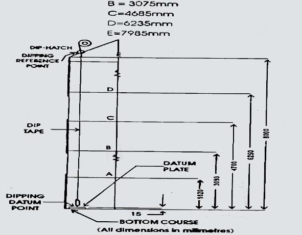
FIG. 59 – AN ILLUSTRATION OF VERTICAL MEASUREMENTS
14. DEADWOOD
(1) Deadwood shall be accurately accounted for, as to size and location to nearest millimetre in order to
permit:
(a) Adequate allowance for volumes of liquid displaced or admitted by the various parts, and
(b) Adequate allocation of the effects at various elevations within the tank.
(2) Deadwood should be measured, if possible, within the tank. Dimensions shown on the manufacture’s drawing
may
be accepted if actual measurement is impractical.
(3) Measurements of deadwood should show the lowest and highest levels, measured from the tank bottom adjacent
tot the shell, at which deadwood affects the capacity of the tank. Measurements should be in increments which
permit allowance for its varying effect on tank capacity at various elevations.
(4) Large deadwood of irregular shape may have to be measured in separate sections suitably chosen.
(5) Work sheets on which details of deadwood are sketched, dimensioned and located, should be clearly
identified
and should become part of the strapping record.
(6) For variable deadwood, such as nozzles and manholes, encountered in the bottom one or two courses of the
tanks, an average deadwood correction shall be made.
15. TANK BOTTOMS: (a) Flat Type
(1) Tank bottom which are flat and stable under varying liquid loads will have no effect on tank capacity
depressed on the basis of geometric principles.
(2) Where tank bottom conditions of irregularity, slope and instability exist, and where correct capacities
cannot be determined conveniently from linear measurements alone, it shall be necessary to resort either to
liquid calibration or to floor survey.
(3) Liquid Calibration – The procedure in carrying out the liquid calibration is to fill into the tank
quantities of known volume of water or other non-volatile liquid until the datum point is just covered and the
total quantity recorded. Additional quantities shall then be added until the highest point of the bottom is
just
covered. This may be done in one or more stages as desired and the dip reading and quantity at each stage
recorded. It is convenient for dip readings to be taken at intervals of approximately 30 mm, the successive
intervals not necessarily being identical. This liquid may conveniently be measured into the tank by a
positive
displacement bulk meter which should be previously calibrated for the liquid and rate of flow to be used.
Alternatively, and accurately calibrated proving measure may be used.
(4) Volumes for the tank capacity table above this elevation shall be computed from linear measurements.
(5) Floor Survey – The floor survey consists in recording levels of the floor by means of a dumpy sections and
the longitudinal sections of the entire floor may be computed, the levels when plotted with define the profile
and the geometric pattern of the bottom of the tank. Thus the capacity of tank may be calculated.
(6) During the tank bottom calibration the circumference in height between the datum plate and the bottom of
the
bottom course should be recorded, wherever possible.
(b) Conical, Hemispherical, Semi-ellipsoidal and Spherical Segment
Tank bottoms conforming to geometrical shapes have volumes which may either be computed from linear
measurements
or measurements by liquid calibration by incremental fining or by floor survey, as desired. Any appreciable
differences in shape affecting volume, such as knuckle redil etc. shall be measured and recorded in sufficient
detail to permit computation of the true volume.
16. MEASUREMENT OF TILT
Measurements shall be taken to determine the amount, if any, by which the tank is fitted. This can conveniently be done by suspending a plump line from the top angle and measuring the offset at the bottom angle (see Fig. 60). Alternatively, if the tank bottom is being calibrated by floor survey with a dumpy level as in 15(a)*5(, the tilt can be estimated by tanking reading along the periphery of the tank bottom. Also, if a liquid calibration of bottoms is being made as outlines in 15(a)(5), the tilt can be determined by taking measurements from the surface of the liquid to the bottom of the tank.
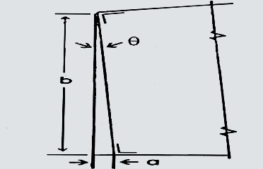
In any of these methods, a sufficient number of measurements shall be taken at different points of the circumference to determine the maximum offset.
17. FLOATING ROOF AND HYBRID ROOF TANKS
(1) All calibration measurements shall be made exactly as for tanks with fixed roofs. A hybrid roof tank
comprised of a covered floating roof where a panroof is installed within a fixed roof tank. A schematic
sectional view of a typical open top floating roof tank is shown in Fig. 61.
(2) Liquid Calibration for Floating Roof Displacement.
(a) Corrections for floating roof displacement arising associated with it shall be allowed for in the
calibration measurement.
(b) If the mass of the floating roof is accurately known, correction for the displaced liquid may be applied
knowing density and temperature of the tank contents, at the time of determining the actual inventory.
(3) alternately, displacement due to the floating roof and deadwood may be determined by admitting liquid to
the
tank until the dip reading is just bellow the lowest point of the roof. Known quantities accurately determined
(for example by bulk meter or delivery from portable proving measure which has been accurately calibrated are
then admitted to the tank and the corresponding dip readings recorded of a number of suitable intervals until
the point is reached when the roof just becomes liquid-borne. Record the density and temperature of liquid
used.
(a) It is advisable to use a liquid of nearly the density as that for which the tank is tntended. If this is
not
practical, water may be used and suitable corrections applied.
(b) During liquid calibration any space under the roof that will trap gas should be vented to the
atmosphere.
(c) Before liquid calibration the height of the lowest joint of the roof with reference to datum point should
be
recorded, wherever possible.
(d) To assess the point at which roof becomes liquid-borne the following procedure may be followed:
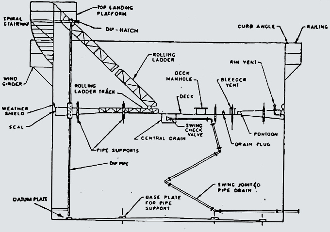
FIG. 61 – A SCHEMATIC SECTIONAL VIEW OF A TYPICAL OPEN TOP FLOATING ROOF TANK
With the roof resulting fully on its supports, point four short horizontal white lines about 30 mm wide on
the
tank sides in such a position that, viewed from some definite point, their lower edges are just above four
similar lines marked on the roof edges or shoes. Then slowly pump liquid into the tank; when all roof markings
are seen to have moved upwards, regard the roof as liquid-borne, and take the dip reading of the liquid at
this
level. Alternatively, from some chosen view point on the dipping platform, note the position of the roof
against
river heads on vertical seam or other markings on the tank walls instead of point marks. In both cases extend
the points of reference round the greater path of the tank interior and see movement relative to all
points.
(4) Floating Mass – The floating mass of the entire roof shall include mass of roof plus half the mass of the
rolling ladder and other hinged and flexibility supported accessories that are carried up and down in the tank
with the roof. These are calculated by the tank manufactures and given on the drawing and on the roof name
plate.
(5) Deadwood
(a) Fixed deadwood shall be measured as described in clause 14. the drain lines and other accessories attacked
to the to the underside of the roof shall be treated as fixed deadwood in the position they occupy when the
roof
is a treated on the supports.
(b) When all or part of the mass of the roof is resting on its supports, the roof itself is deadwood and as
the
liquid rises around the roof, its geometric shape will determine how it should be deducted. The geometric
shape
should be taken from the manufacture’s drawings or measured in the field with aid of and engineers level while
the roof is resting on its supports.
18. VARIABLE VOLUME ROOFS
(1) Roofs such as lifter, flexible membrane, breather or balloon, may require special deadwood measurements
for
roof parts that are sometimes submerged. When these parts, such as columns, are fixed relative to the tank
shell, they should be measured as deadwood in the usual way. When these parts move with roof and hang down
into
the liquid, they should be deducted as fixed deadwood with roof in the lowest position. Details may be secured
from the manufacture’s drawings or measured in the field.
(2) Some variable volume roofs have flexible membrane which may float on the surface when the membrane is
deflated and liquid level is high. The floating mass of the membrane displaces a small volume of liquid. Data
on
the floating mass should be secured from the manufacture's drawings and supplemented, if necessary, by fields
observation and measurement.
(3) Some variable volume roofs have liquid seal troughs or other appurtenances with make the upper outs depart
of the shell inaccessible for calibration of this position of the shell may be made, or (a) theoretical
dimensions may be taken from the measurable circumferential measurement may be used as a basis for the portion
if the tank that cannot be measured. When the method (a) or (b) is used, it shall be so indicated on the tank
capacity table.
SECTION 2 – CALIBRATION BY INTERNAL TAPE MEASUREMENT METHOD
19. GENERAL
(1) This method is based on the measurement of internal dimensions of all vertical tanks of any geometric
shape.
(2) In the case of a cylindrical tank is simulated number of internal diameters shall be obtained as described
under clause 21.
(3) Where practicable, an external circumference shall be measurement approximately the same as that at which
a
set of diameters of which a internal diameter shall be compared and if a discrepancy is found, the
measurements
shall be verified.
(4) It may be necessary in practice to refer all tank dips to a datum point other than the datum point used
for
the purpose of tank calibration, so, the difference in levels between these datum points shall be determined
either by normal surveying methods or by other suitable means.
20. EQUIPMENT
(1) Dynamometer – This is used for applying tension to steel tape.
(2) Other equipment as referred to under clause no. 10.
21. SELECTION OF PREDETERMINED POINTS
(1) A predetermined (PD) point is one of a series of points marked clearly on the inside
surface of the tank shell wall to which diameters are measured by the use of tape measurement method. Two sets
of predetermined points per course, one at 1/5 to 1/4 of course height above the lower horizontal seam, the
other at 1/5 to 1/4 of course height below the upper horizontal seam, shall be selected.
(2) The number of predetermined points per set, on each course of the tank shell wall is dependent on the tank
circumference. The minimum number of predetermined points per set as function of tank circumference in given
in
Table 52 and illustrated in Fig. 62.
(3) The predetermined points shall be at least 300 mm from any vertical seam.
22. DIAMETER MEASUREMENTS
(1) All diameter measurements shall be made with a tension of 4.5 ±0.5 kg applied to the tape as indicated by
the dynamometer.
(2) All tape measurements shall be recorded as read, that is without including the length of the
dynamometer.
(3) The dynamometer length at 4.5 kg shall be taken accurately before it is put into commission, and
subsequently checked before and after calibrated of each tank, the final check being made before leaving the
site.
(4) Measurements shall be taken with the zero end of the steel tape attached to the dynamometer on the
predetermined point and the second operator placing the rule end-on to a point diametrically opposite. The
tape
with graduated side wholly upwards is then pulled along the rely until the requisite tension is registered by
the sounding of the buzzer in the dynamometer. The relative position of tape and rule is maintained by a film
grip until the rule is removed from the side of the tank and the measurement read on me tape at the end of the
rule which was previously in contact with the tank side. The operation shall be repeated at the various
positions at which measurements are required throughout the tank. The measurements shall be recorded clearly
in
white chalk on the steel plates in such a manner as to indicate the positions at which they were taken.
| Table 52 – Minimum number of predetermined points per set | |
|---|---|
| Tank Circumference, cm | Minimum number of PD points |
| C < 50 | 8 |
| C < 50 | 8 |
| C < 50 | 8 |
| C < 50 | 8 |
| C < 50 | 8 |
| C < 50 | 8 |
| C < 50 | 8 |
| C < 50 | 8 |
| Note: A number of target points greater than the minimum number of points as a specified above may be selected depending on specific circumferences and tank conditions. | |
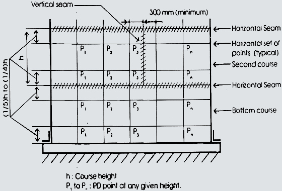
FIG. 62 – PREDETERMINED POINTS POSITIONING OF TANK SHELL WALL
All other measurements shall be followed in accordance with Section 1. SECTION 3. CALIBRATION BY INTERNAL ULTRASONIC DISTANCE RANGING METHOD
23. OTHER MEASUREMENTS
24. GENERAL
This method is based on the measurement of internal dimension so f all vertical tanks of any geometric shape by means of an ultrasonic distance ranging (UDR) instrument and subsequent compilation of tank capacity tables.
25. EQUIPMENT
(1) Ultrasonic distance ranging (UDR) instrument: The instrument is low-power ultrasonic wave emitter as
well as
received for reflected waves under for direct determination of distances and shall have a scale interval not
greater than 1 mm and an uncertainly equal to or less than ±2 mm.
(2) Other equipment as referred to under clause 20.
26. CONDITIONS FOR MEASUREMENTS
(1) Calibration shall be carried out without interruption.
(2) The UDR Instrument shall be verified prior to calibration against a known reference length comparable to
the
diameter of the tank.
(3) The tank as well as the UDR instrument shall be free from external vibration.
(4) The UDR instrument shall be set perpendicular to the tank shell wall, thus ensuring the circularity of the
plane of measurements and minimizing the overall uncertainty of the diameter measurements.
(5) The PD points shall be so selected that the path of transmitted waves from the UDR instrument to the
diametrically opposite tank shell wall shall not be obstructed.
(6) Other conditions shall comply with the provisions described in clause 3.
27. SELECTION OF PREDETERMINED (PD) POINTS
The selection of PD points shall comply with provisions described in clause 21.
28. CALIBRATION PROCEDURE
(1) Diameter shall be measured at all PC points at each course location as illustrated in Fig. 62 in
clause
21.
An average of five maximum readings shall be recorded.
(2) The measurements to the PD points on each course by internal tape measurement method. The resulting
diameters shall be completed prior to moving to the next course.
(3) A reference diameter shall be measured approximately in middle of each course by internal tape
measurement
method. The resulting diameters shall be compared, and if a discrepancy is found, the measurements shall
be
verified.
29. OTHER MEASUREMENTS
All other measurements shall be followed in accordance with Section 1 and Section 2. SECTION 4 – CALIBRATION BY INTERNAL ELECTRO-OPTICAL DISTANCE RANGING METHOD
30. GENERAL
This method is based on the measurement of internal diameters of vertical cylindrical tanks having diameters equal to or greater than 5 metres by means of an electro-optical distance ranging (EODR) instrument and subsequent compilation of tank capacity tables.
31. EQUIPMENT
(1) electro-optical distance ranging (EODR) Instrument:
(a) The angular measuring part of the instrument shall have an angular graduation equal to or less than
0.0002
degree and uncertainly equal to or less than ±0.001 degree.
(b) The distance – measuring part of the instrument, used for direct determination of distances, shall
have
scale interval equal to 1 mm and an uncertainly equal to or less than ±2 mm.
(2) Laser beam emitter – This instrument is a low-power laser beam emitter which is either on integral
part
of
the EODR instrument or a separate device. If the laser beam emitter is a separate device., it may be
fitted
with
a fibre optic light transmitter system and a theodolite telescope eyepiece connection, be which the laser
beam
may be transmitted through the theodolite, or such that it may be fitted to a theodolite with its axis
parallel
to the axis of the theodolite. The laser beam may be coincident with the optical axis of the telescope.
The
laser beam emitter is used to position target points on the tank shell.
(4) Instrument Mounter – The instrument mounter consists of a tripod shall be held firm, and steadled by
suitable devices such as magnetic bearers.
(5) Metalic Length Measure of 1 Metre – Complying with the specifications given under Path IV of the Sixth
Schedule.
32. CONDITIONS FOR MEASUREMENTS
(1) Calibration shall be carried out without interruption.
(2) The tank as well as the EODR instrument shall be free from external vibration and the tank shall be
free
from air-borne dust particles.
(3) The EODR instrument shall be verified prior to calibration according to procedures described in clause
35.
(4) Other conditions shall comply with the previous described in clause 3.
33. SELECTION OF TARGET POINTS
(1) A target point is one of the series of points marked clearly on the inside surface of the tank shell wall to which slope distance, vertical and horizontal angles are measured by use of the EODR instrument. The distance measured from the EODR instrument to a target point on any given course of tank shell wall is said to be slope distance. Any fixed target point with reference target point. Two sets of target points per course, one 1/5 to 1/4 of course height above the lower horizontal seam, the other at 1/5 to 1/4 of course height below the upper horizontal seam, shall be selected. (2) The number of target points per set, on each course of the tank shell wall is dependent on the tank circumference. The minimum number of target points per set, as a function of tank circumference is given in Table 53 and illustrated in Fig. 63.
FIG. 63 – TARGET POINTS POSITIONING OF TANK SHELL WALL
(3) The target points shall be at least 300 mm from any vertical seam.
(4) Two reference target points shall be selected and marked clearly on the tank shell wall approximately
90°
apart and preferably on the same horizontal plane as the instrument.
34. EQUIPMENT SETUP PROCEDURE
(1) The instrument shall be set up so as to be stable, if necessary, the tank bottom in the vicinity of
the
instrument shall be made firm and steady by placing heavy weights in the area. The legs of the tripod on
which
the instrument is mounted shall be steadied by use of suitable devices, such as magnetic bearers, to
prevent
slippage on the tank bottom.
(2) The instrument shall be located at, or near the centre of the tank. This will ensure that the measured
slope
distances, at an horizontal level, do not vary significantly and minimizes the overall uncertainty of
slope
distance determination.
(3) The instrument shall be set horizontal, thus ensuring that the standing axis is vertical.
(4) The sighting lines from the instrument to the tank shell wall shall not be obstructed.
35. TOLERANCES AND FIELD VIREFICATION OF EQUIPMENT
(a) Angular measurement verification
(1) The EODR instrument shall be set up according to procedures described in clause 34 and shall be
switched
on
and brought to operating temperature, allowing at least the minimum warm up time.
(2) Each EODR instrument will have manufacture’s instructions concerning collimation of both the vertical
and
horizontal angular measurement components of the instrument. These instructions shall be followed exactly,
and
the uncertainly of both the vertical and horizontal angular measurement calculated and recorded.
(3) The collimation uncertainly of both vertical and horizontal components of the instrument shall not
exceed
the tolerance of ±0.001 degree.
(b) Distance measurement verification
(1) The metre bar shall be mounted on a tripod horizontally and perpendicular to the to the aiming axis of
the
EODR instrument and shall be locked in position.
(2) The metre bar shall be placed at a distance of approximately 5 metres from the instrument and
perpendicular
to an imaginary line between the instrument and the centre of the metre bar, as illustrated in Fig.
64.
(3) The horizontal angle 29 subtended at the instrument by the zero mark and the 1 m mark of the metre bar
shall
be measured, using the EODR instrument.
(4) The horizontal distance D shall be computed from the equation.
D = B/2 x cote where B = 1 m.
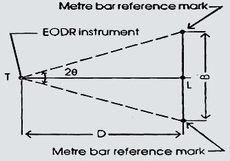
(5) The slope distance r : measured by the EODR instrument and the average computed distance D shall agree to within a tolerance of ±2 mm.
36. CALIBRATION PROCEDURE
(1) All of the target points along the horizontal plane at each course location shall be sighted and the
slope
distance, horizontal angle and the vertical angle to each, shall be measured as illustrated in Fig.
65.
(2) The slope distance, horizontal angle and vertical angle to each of the reference target points shall
be
measured and recorded.
(3) The measurements to the target points on each course shall be completed prior to moving to the next
course.
Measurements shall begin at the bottom course and extend, course by course, to the top of the tank.
(4) The measurements to the reference target points shall be repeated after all measurements on a course
being
completed.
(5) If the repeated slope distance, horizontal angles and vertical angles to the reference target points
do
not
agree within the tolerances given in clause 35, then the procedure 1 – 5 shall be repeated.
(6) If statistical agreement is not obtained between the original and repeated measurements of slope
distances,
horizontal angles or vertical angles, then the reasons for such disagreements shall be determined, the
cause
eliminated and the tank calibration procedure repeated.
37. OTHER MEASUREMENTS
All other measurements shall be followed in accordance with Section 1.
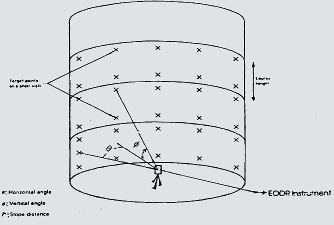
FIG. 65 – MODE OF MEASUREMENTS OF TARGET POINTS ON TANK SHELL WALL
METHODS FOR COMPUTATION OF CAPACITY TABLES FOR VERTICAL STORAGE TANKS GENERAL SECTION
1. SCOPE:
This part prescribes the methods for computation of capacity tables for vertical storage tanks with or
without a
tilt used for bulk storage of liquids of atmospheric pressure or under low or high pressure with or
without
heating or cooling mounted aboveground or underground or on ships or barges either by strapping method
(SM)
by
internal ultrasonic distance ranging method (IUDRM) or by internal electro – optical distance ranging
method
(IEODRM).
PREPARATION OF TANK CAPACITY TABLES
(1) The calculations shall be made in accordance with accepted mathematical principles.
(2) Each certificate of calibration shall consist of three statutory parts, namely:
Part A – General Information
Part B – Correction table for liquid head in the course wise open capacity per unit depth in the case of
cylindrical tanks with circular cross section and correction table for tilt and deadwood.
Part C – Dip/Capacity Relationship Table and Proportional parts table with explanatory notes (if any).
Every page of the certificate of calibration shall be signed with date by the calibration authority.
(3) For certain products, e.g. heated bituments, capacity tables are more conveniently prepared in terms
of
usage; but where the gauging process is in terms of dip only, the capacity tables may be prepared in terms
of
equivalent dips.
(4) The capacity tables shall be prepared at the tank shell reference temperature of 15°c.
FORM OF TANK CAPACITY TABLES
(1) Provided that tank capacity tables have been prepared in accordance with the principles laid down in
this
specification, the form is which the table is set out shall not alter the accuracy of the figures obtained
from
it.
(2) The dip intervals of which the capacity table are set out shall not be so great that interpolation for
in
intermediate dips is difficult.
(3) Level affected by boom irregularities and floating roof non-linearity range shall not be included in
calculating the average capacity per unit depth used for the proportional parts table for tanks with
uniform
cross section and this table shall not be applied in the interpolation in these ranges. This ranges shall
be
clearly marked on the tank capacity table. When the levels are affected by deadwood, the corrected open
capacity
per unit depth shall be averaged for each course to set out proportional parts table for each course. The
proportional parts table for intermediate dips
shall be set out in millimetres. No proportional parts table shall be set out in the case of tanks having
non-uniform cross sections for which intermediate fractional capacities may be obtained by interpolating
the
average capacity per millimetre between two consecutive dips.
(4) The capacity tables may be set out more fully; this can be justified in some cases where the greatest
speed
in calculation is desired but it shall be remembered that a capacity table set out on a single sheet of
paper is
often quicker in use than one which occupies several pages.
(5) If should be remembered that, at best, no liquid measurement can be relied upon to nearer than one
part
in
10,000. capacity tables should not be set out to show any fractions of a litre.
(6) In order to keep the sizes of capacity tables limited to around 500 readings. It is recommended that
tank
capacity tables shall be set out to show litres at dip intervals as a fraction of filling height of the
tank
as
specified in Table 54.
| Table 54 – SPECIFIED DIP INTERVALS | |
|---|---|
| Filling Height (H) (m) | Dip Interval (mm) |
| H ≤ 5 | 10 |
| 5 ≤ H ≤ 10 | 20 |
| 10 ≤ H | 50 |
(7) The recommended formats of Part A, Part B and Part C of the certificate of calibration are given in
Table 59
to Table 53 in clause 14.
4. COMPUTATION CAPACITIES
(A) For uniform cross sections
(1) Calculation
(a) The mean external circumference of any course (ring) shall be the average of the circumferences measured
on
it and corrected to the nearest 0.1 mm.
(b) The mean internal circumference of the course (ring) shall then be calculated from the mean external
circumference of the course (ring) by subtracting from the latter 2 times the plate thickness in metres.
(c) The open capacity of each course (ring), that is, its capacity without allowing for deadwood shall be
calculated as if the course (ring) were a true cylinder of the mean internal circumference determined as
under
(b) as above. This rule shall apply to vertical cylinders of in-and-out, telescopic or shingles
construction.
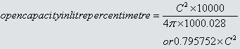
(d) The open capacity of each course (ring) in litres per centimetre of height shall be obtained by using
either
the following formula or any other mathematically equivalent process.
Where
C = the mean internal circumference in metres.
(2) The open capacity in litres of an elliptical tank up to a height, h when all dimensions are expressed
in
millimetres, shall be obtained by using the following formula:
Open capacity in litres = n x 106 x A x B x h<
4 x 1.000028 = 7.85376 x 10⁻⁷ x A x B x h where A = the internal major axis, B = the internal minor axis.
Open
capacity in litres per millimetre = 7.85376 x 10⁻⁷ x A x B
(3) The open capacity in litres of a rectangular tank up to a height, h when all dimensions are expressed
in
millimetres, shall be obtained by using the following formula:
Open capacity in litres = 106 x l x b x h; 1.000028 = 9.99972 x 10⁻⁷ x l x b x h where l = the mean
internal
length, b= the mean internal breath.
18 Open capacity in litres per millimetre = 9.99972 x 10⁻⁷ x l x b x h
(B) For non-uniform cross sections:
(1) The open capacity in litres of a conical tank of frustum height, H and up to liquid height, h when all
dimensions are expressed in millimetres, shall be obtained by using the following formula depending on the
nature of tapering:
Open capacity in litres of a conical frustum = n x 10-6 x h S130|_30|10|_0||*||0_15|1|*|1
= 2.61792 x 10⁻⁷ x h [3D12 – 3D1 (D1 – D2) (H / h) + (D1 – D2)2 (H / h)2]
Where D1 = mean internal diameter of the base, D2 = mean internal diameter of the top.
In the case of con-up frustum as shown in Fig. 66(a), the diameter at the base is greater than that at the
top
(D1 > D2) and in the case of a cone-down frustum as shown in Fig. 66(b), the diameter at the base is
smaller than that at the top (D1 < D2).
(2) The open capacity in litres of vertical tank having segments of different geometric shapes shall be
obtained by the accepted mathematical principles.
TEMPERATURE CORRECTION
(1) Correction during calibration – Strapping tapes and dip tapes calibrated at a reference temperature which is normally 20°c. For practical purposes, the linear measurements are assumed to be correct at the tape reference temperature. The tape is in close contact with tank shell and thus can be considered to be at the same temperature as the tank shell. If the tank capacity table is prepared at a reference tank shell temperature of 15°c, the linear measurements shall be corrected either by multiplying by a factor equal to 0.00009 and then by subtracting the result from the measured dimensions or by multiplying by a factor equal to 0.99991 before the figure is taken into further consideration.
(2) Correction during normal service – The determination of a specific volume at an observed tank shell temperature Ts and liquid temperature Tl is effected by multiplying a factor to the volume corresponding to given liquid dip as obtained from a tank capacity table certified at 15°c. (a) In the case of tanks without thermal insulation, the factor F is given by the equation: F = [ {1 + a (Tl – 15)}{1 + 2a (Ts – 15)}]
(b) In the case of tanks with thermally insulated shells, the factor F is given by the equation: F = 1 + a (Tl – 15) Where a = the coefficient of linear expansion of the tank shell metal which is normally 0.000011°c for mild steel.
6. LIQUID HEAD CORRECTION
The effect of any liquid head shall be introduced into tank capacity tables by means of methods which
involve
the calculation of expansion effects at progressively increasing liquid levels in a cylindrical tank of
circular
cross section.
(a) Addition of expansion effects in the tank capacity tables:
The volume expansion per unit depth for each course of the tank shall be computed by means of the following
equations which shall be added to the unstressed open capacities in litres per millimetre obtained from
cause
4(A)(1).
The equations are as follows: 1st course: V1 = K [0.8 h1 / 2f1]
2nd course: V2 = K [0.8 h1 / f1 + h2 / 2f2]
3rd course: V3 = K [0.8 h1 / f1 + h2 + h2 / 2f3]
4th course: V4 = K [0.8 h1 / f1 + h2 + h2 / 2f2 + h3 / 2f3 + ………….. + h4 / 2f4]
Where V1, V2, V3, V4 are the incremental increases in the capacity of the tank, in litres per millimetre of
course height, of the first course, second course, third course and fourth course, caused by liquid head;
h1,
h2, h3, h4 are the heights, in millimetres, of the first course, second course, third course and fourth
course
t1,t2,t3,tn are the thickness, in millimetre of the plates of the first course, second course, third course
and
nth course.
K is a constant for any given course, given by the following equation:
gC3 (p – 1.1) ngD3 (p – 1.1)
K= CX K ---
8n2E 8E
Where C is the course circumference in millimetres. D is the course diameter, in millimetres; P is the
density
in kilograms per cubic metre, of the liquid which the tank will contain in service. E s Young’s modules of
elasticity of the tank shell metal in newfons per square metre: g is the acceleration due to gravity, in
metres
per second squared.
Note: A correction for an density of 1.1 kg/m3 is included in the equation to convert density to apparent
density in air.
An example of calculation routine for expansion in service is in Table 58.
(b) Addition of expansion effects in the computerised liquid stock accounting systems.
The volume expansions per unit depth as computed in clause 6(a) above shall not be required if the tank
calibration is to be used in computerised liquid stock accounting systems which calculate expansion due to
liquid head based on measured liquid levels and density of the time of calculation. The total volume
expansion
due to liquid head pressure exerted by the liquid at level L shall be computed by means of the following
equations which shall be added to the unstressed open capacities in litres per millimetre obtained from
cause
4(A)(1). The equations are as follows:
1st course {{tmp1 }}
Where C is the course circumference in millimetres. D is the course diameter, in millimetres; P is the
density
in kilograms per cubic metre, of the liquid which the tank will contain in service. E s Young’s modules of
elasticity of the tank shell metal in newfons per square metre: g is the acceleration due to gravity, in
metres per second squared.
Note: A correction for an density of 1.1 kg/m3 is included in the equation to convert density to apparent
density in air.
7. TILT CORRECTION
(1) The open capacities in litres per millimetre computed in clause 4 apply to tanks which are vertical.
For
tanks inclines to the vertical at an angle 0, the open capacities in litres per millimetre of vertical
height
shall be obtained by multiplying the open capacities in litres per millimetre as computed in clause 4 by a
factor sec 0.
The value of sec 0 may be ignored for angles of tilt up to 1 in 70. This representing the maximum error of
0.01 percent.
(2) The correction specified above shall be applied before the corrections for deadwood are made.
(3) In the case of tanks mounted on ships or barges, all liquid dips are taken in a plane perpendicular to
the
even keel water line during calibration. Under different load conditions, a tilt in respect of trimming or
listing or of both may result during normal service. The correction factors shall be added to or subtracted
from the observed volume in the tilted position to get the corrected volume. The correction factors for trim
or list or for both shall be calculated by accepted mathematical principles from the known angles of tilt,
observed liquid dips and the positions of the dip hatches.
8. DEADWOOD
(1) The open capacity of each course shall be adjusted for any deadwood it contains.
(2) The total volume of each piece of deadwood shall be calculated to the nearest litre. In this context,
the
term ‘piece of deadwood’ shall include such items as the rivet heads in one line around the tank, taken
collectively, as a single piece of deadwood.
(3) The effect of small pieces of deadwood may neglected provided that the total effect of any such neglect
shall not lead to error in the tank capacity tables exceeding 0.005 per cent of the total capacity of the
course in which the deadwood occurs, and any deadwood so neglected is distributed evenly, or substantially
so
over the whole height of the course in calculating the table, however, it shall be permissible to include
the
effect of any deadwood, however small.
9. TANK BOTTOMS
(1) When the tank bottom is substantially horizontal, for example, when the tank is carried on a level
concrete raft of steel structure, then bottom irregularities can be neglected.
(2) When the tank bottom has been calibrated by measuring in suitable known volume of liquid, the tank table
for these levels shall be prepared from these measurements on sound mathematics principles. The highest
level
and capacity shown in the tank bottom calibration table so prepared shall then be the datum level and
capacity
from which is prepared by calculation as described in this section.

10. FLOATING ROOF TANKS
Except for the following modifications tables shall be prepared in accordance with Section 1 to Section
4.
(1) Allowance for deadwood shall be made as described in clause 8.
(2) The drain line and other accessories attached to the underside of the roof shall be included as fixed
deadwood in the position they occupy then the roof is at rest on its supports. The position of these
accessories should be specified in the tank capacity table.
(3) Two levels shall be defined, both as exact number in multiples of 10 mm above the datum point form which
dip reading will be taken. The first level, designated A, shall be not less than 40 mm and not more than 60
mm below the lowest point of the roof plant when the roof is at rest. The second level , designated B, shall
be not less than 40 mm and not more than 60 mm above the free liquid surface when the roof is at its lowest
liquid borne position.
(4) The floating mass of the entire roof shall include mass of roof plus half the mass of the olling ladder
and other hinged and flexibly supported accessories that are carried up and down in the tank with the
roof.
The displaced volume in litres due to roof mass can be easily calculated from:
roof mass in kg x 103
The displacement, minus the volume of deadwood already accounted for in-above, shall be considered as an
item of deadwood applicable to all levels above B. It shall either be entered as such on a supplementary
table or taken into account in the preparation of the final able as a deduction for deadwood at all levels
above B. For levels between A and B, the proportion of roof displacement to be taken into account as
deadwood may be calculated from the dimension of the floating roof. These partial displacements shall either
be entered as such in the supplementary table as applicable for levels between A and B or taken into account
in preparation of final table. Alternatively, where measured quantities, or liquid have been admitted to the
tank and corresponding levels of the free liquid surface determined by dipping, the necessary adjustments to
the tank capacity within the range of the level A and B may be computed from this data. The part of the
table between level A and level B shall be marked ‘non-linear’.
(5) If is considered impracticable to allow in the tank capacity table, for the effects of extraneous matter
retained by the roof, varying fractions of the roof shoes and varying immersion of roof supports.
SECTION 1 – STRAPPING METHOD
11. CORRECTIONS FOR MEASURED CIRCUMFERENCE
(1) Step-Over
(a) For each obstruction the excess or deficiency of the tape measurement spanning the obstruction as
compared with step over interval for the course concerned shall be subtracted from or added to the
circumference figure obtained by strapping, and the result shall be taken as the corrected circumference,
free from error due to the displacement of the tape from its proper path by the obstruction concerned.
(b) Step over correction shall be included for all vertical seams where it is detectable in the case of
vertical seams, provided that the tape path used was entirely clear of rivet heads, an average step-over
correction may be determined for each course and multiplied by the number of seams per course to obtain the
total correction to be applied to the measured circumference of that course to compensate for such
overlaps.
(c) For single obstructions, only step-over corrections 2 mm or over shall be included.
(d) The use of the step-over corrects circumferences for: the effect on them of vertical seam overlaps but
does not correct the tank tables for the effect as deadwood of internal projections of the seam edges. These
shall be computed and accounted for as deadwood.
(e) By choosing rape courses in order to avoid appurtenances use of step over could be eliminated to a great
extent.
(2) Plate Thickness – Plate thickness measured shall be recorded to the 0.1 mm.
(3) Temperature – Each measured circumference shall be corrected in accordance with the provisions as laid
down in clause 5(1).
12. SYSTEMATIC CALCULATIONS
(1) The correct external circumference shall be obtained after step-over correction from the strapped
circumference and the mean external circumference of any course is calculated and corrected to the nearest
0.1 mm.
(2) The mean internal circumference of the course shall then be calculated from the mean external
circumference of the course by subtracting from the latter 2n times the shell plate thickness.
(3) The mean internal circumference shall then be corrected for temperature as specified in clause 5(1).
(4) The open capacity of each course shall be calculated as if the course were a true cylinder of the mean
internal circumference determined as under (3) below.
(5) The open capacity of each course in litres per millimetre shall be obtained by using the formula as
given as clause 4(A)(1)(a).
(6) The open capacity of each course in litres per millimetre shall then be corrected for liquid head, tilt
and deadwood.
(7) Specimen calculations are given in clause 13.
| Course No. | Applicable Height (mm) | Deadwood (Litres/mm) | Total Deadwoods in Courses (Litres) | |
| 8 | 14660 to 14750, 14150 to 14660, 13500 to 14150, 12880 to 13500 | -350, -508, -2336, Nil | -3.88889, -0.99608, -3.59385, Nil | -3914 |
| 7 | 11090 to 12880 | Nil | Nil | |
| 6 | 9190 to 11090 | Nil | Nil | |
| 5 | 7400 to 9190 | Nil | Nil | |
| 4 | 5490 to 7400 | -195 | -0.10209 | -195 |
| 3 | 3710 to 5490 | -259 | -0.14551 | -259 |
| 2 | 1800 to 3710 | -309 | -0.16178 | -309 |
| 1 | 1070 to 1800, 510 to 1070, 460 to 510, 0 to 160 | -145, +59, -36, Nil | -0.19863, +0.10536, -0.72000, Nil | -122 |
(3) DATA OBTAINED FOR DEADWOOD ARE GIVEN IN TABLE 56 – TABLE 56 – DATA FOR DEADWOOD
13. SPECIMEN CALCULATIONS FOR STRAPPING METHOD
(1) DATA OBTAINED BY STRAPPING ARE GIVEN IN TABLE 55. TABLE 55 – DATA FOR LINEAR MEASUREMENTS
|
Course No.
|
Measured External Circumferences (mm)
|
Step-over Corrections (mm)
|
Plate Thickness (mm)
|
Internal Height Courses of
|
|
|
Individual (mm)
|
Cumulative (mm)
|
||||
|
8 Top
8 Middle
8 Bottom
|
113
040
113
|
2
2
2
|
7
7
7
|
18
20
|
14750
|
|
7 Top
7 Middle
7 Bottom
|
113
127
113
|
2
2
2
|
7
7
7
|
1790
|
12880
|
|
6 Top
6 Middle
6 Bottom
|
113
090
113
|
3
3
3
|
10
10
10
|
19
00
|
11090
|
|
5 Top
5 Middle
5 Bottom
|
113
152
113
|
4
4
4
|
13
13
13
|
9190
|
|
|
4 Top
4 Middle
4 Bottom
|
130
85
113
|
10
10
10
|
13
13
13
|
19
10
|
7400
|
|
3 Top
3 Middle
3 Bottom
|
113
175
113
|
10
10
10
|
16
16
16
|
17
80
|
5490
|
|
2 Top
2 Middle
2 Bottom
|
113077
113081
113075
|
13
13
13
|
18
18
18
|
19
10
|
3710
|
|
1 Top
1 Middle
1 Bottom
|
113
187
113
|
15
15
15
|
20
20
20
|
18
00
|
1800
|
(2) Additional Data
(a) Ambient temperature = 20°C (b) Density of liquid intended to be contained, p = 850 kgm3 (c) Young’s modules of elasticity of the tank shell metal, E = 200 x 109 Nm2 (d) Accoderalton due to gravity, g = 9.80665ms2 (e) Angle of tilt 6 = 0°
|
Course No.
|
Applicable Height (mm)
|
Deadwood (Litres/mm)
|
Total Deadwoods in Courses (Litres)
|
|
| 8 |
14660 to 14750, 14150 to 14660, 13500 to 14150, 12880 to 13500
|
-350, -508, -2336, Nil
|
-3.88889, -0.99608, -3.59385, Nil
|
-3914
|
| 7 |
11090 to 12880
|
Nil
|
Nil
|
|
| 6 |
9190 to 11090
|
Nil
|
Nil
|
|
| 5 |
7400 to 9190
|
Nil
|
Nil
|
|
| 4 |
5490 to 7400
|
-195
|
-0.10209
|
-195
|
| 3 |
3710 to 5490
|
-259
|
-0.14551
|
-259
|
| 2 |
1800 to 3710
|
-309
|
-0.16178
|
-309
|
| 1 |
1070 to 1800, 510 to 1070, 460 to 510, 0 to 160
|
-145, +59, -36, Nil
|
-0.19863, +0.10536, -0.72000, Nil
|
-122
|
(3) DATA OBTAINED FOR DEADWOOD ARE GIVEN IN TABLE 56 – TABLE 56 – DATA FOR DEADWOOD
(4) Calculation of Corrected Internal Circumference:
For Course No 8 Top:
Measured External Circumference = 113040.0 mm
Step-over correction = -2.0 mm
Correction for plate thickness (7 x 2n) = -44.0 mm
Temperature correction = 10.2 mm
Corrected Internal Circumference at 15°C = 112983.8 mm
The calculations for other courses may be done in a similar way.
The corrected internal circumferences for the remaining measurements given above are shown next.
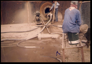
(5) The open capacity of courses are given in table 57
|
TABLE 57 – OPEN CAPACITY OF COURSES
|
||||
|
Course No.
|
Corrected Internal Circumference (mm)
|
Mean InternalCircumference (mm)
|
Open Capacity of Courses
|
|
|
l/mm
|
Litres
|
|||
|
8 Top
8 Middle
8 Bottom
|
112983.8
113029.8
113029.8
|
113014.8
|
1016.36191
|
1900597
|
|
7 Top
7 Middle
7 Bottom
|
113070.8
119076.8
119073.8
|
113073.8
|
1017.42346
|
1821188
|
|
6 Top
6 Middle
6 Bottom
|
113014.0
113020.0
113016.0
|
113016.7
|
1016.39608
|
1931153
|
|
5 Top
5 Middle
5 Bottom
|
113056.1
112064.1
113059.1
|
113059.8
|
1017.17146
|
1820737
|
|
4 Top
4 Middle
4 Bottom
|
112983.1
112990.1
112988.1
|
112987.1
|
1015.86375
|
1940300
|
|
3 Top
3 Middle
3 Bottom
|
113054.3
113005.3
113049.3
|
113053.0
|
1017.04910
|
18’0347
|
|
2 Top
2 Middle
2 Bottom
|
112940.7
112944.7
112938.7
|
112941.4
|
1015.04214
|
1938730
|
|
1 Top
1 Middle
1 Bottom
|
113036.1
113038.1
113034.1
|
113072.8
|
1016.68569
|
1830034
|
|
Total
|
14993086
|
|||
(6) Calculation of volume expansion per unit depth due to liquid head in service:
For Course No. 8
The corrected mean internal circumference C8 = 113014.8 mm
Kn = [gC3 (p-1.1)] / 8:t2E as given in clause 6(a) where
p = 850 kgm, g = 9.8C665 ms2, E = 200 x 10 Nm2
In a similar way.
N = 3.141592654, Kn = 527178 x 1019xCn3, K8 = 0.0007610
The volume expansion per unit depth for the 8th course:
V8 = K8 (0.8 h1/t1+h2/t2+h3/t3+h4/t4+h5/t5+h6/t6+h7/t7+h8/t8)
= 0.0007610 x l h/t
= 0.0007610 x 1153.263 = 0.87759
The calculations for other courses may be done.
(7) The volume expansions per unit depth (AV) of different courses are given in Table 58.
| TABLE 58 – CORRECTION FOR VOLUME EXPANSION PER UNIT DEPTH OF COURSES DUE TO LIQUID HEAD | ||||||
|---|---|---|---|---|---|---|
| Course No. | Course Circumference (c) (mm) | Course Height (h) (mm) | Plate Thickness (mm) | Summation (h/t) | K | V (l/mm) |
| 8 | 113014.8 | 1870 | 7 | 1153.263 | 0.0007610 | 0.87759 |
| 7 | 113073.8 | 1790 | 7 | 891.835 | 0.0007622 | 0.67972 |
| 6 | 113016.7 | 1900 | 10 | 668.978 | 0.0007610 | 0.50909 |
| 5 | 113059.8 | 1790 | 13 | 505.132 | 0.0007619 | 0.38485 |
| 3 | 113053.0 | 1780 | 16 | 223.737 | 0.0007608 | 0.17806 |
| 2 | 112941.4 | 1910 | 18 | 25.056 | 0.0007595 | 0.09498 |
| 1 | 113032.8 | 1800 | 20 | 36.000 | 0.0007613 | 0.02741 |
14. CERTIFICATE OF CALIBRATION: PART – A. GENERAL INFORMATIONS. A format of general information is given in Table 59.
| TABLE 59 – GENERAL INFORMATION | |
|---|---|
|
1. Name and address of the owner or user of the tank: XYZ 2. Tank No. A-001 3. Type of tank joints: Riveted/Lap-welded/Butt-welded 4. Nominal tank capacity: 14993086 litres 5. Type of Roof: Fixed/Floating/Hybrid/Variable Volume 6. Mass o’ boating roof: Nil 7. Type of bottom: Flat/Cone-up/Cone-down with or without knuckle radius/Spherical segment/Hemispherical / Semi-ellipsoidal segment 8. Height or depth of Crown: 15 mm 9. Overall height: 15500 mm 10. Height of datum plate: 1.5 mm 11. Angle of tilt from vertical: 0° 12. Name of liquid intended to be contained: Diesel 13. Temperature of liquid recurred to be maintained in the tank if it is thermally insulated: Nil°C 14. Density of liquid at the ambient maintained temperature: 850 kg/m2 |
15. Average ambient temperature during calibration: 20°C 16. Young’s modules of elasticity of tank shell material: 2 x 1.011 Nm2 17. Coefficient of linear expansion of tank shell material: 1 17 x 10-5 °C 18. Whether equipped with automatic level gauge: Yes/No 19. Whether equipped with computerized liquid stock accounting systems: Yes/No 20. Method of calibration: SM/ITMM/IUDRM/IEODRM |
| Note: The 1st of information is not exhaustive and any other information which may be of use should be included. | |
PART C-1: Dip/Capacity Relationship Table. A format of the dip/capacity table is given
in Table 62. The figures in the table indicate the volumes in litre.
TABLE 62 – A FORMAT OF DIP/CAPACITY TABLE |
|||||||
|---|---|---|---|---|---|---|---|
| Dip (mm) | 0 | 50 | 150 | 200 | 250 | 300 | 350 |
| 0 500 1000 1500 .... |
175 508678 1017080 1525359 .... |
51011 559511 1067921 1576184 .... |
101846 610352 1118753 1627010 .... |
152682 661192 1169579 1677836 .... |
203518 712034 1220404 1728661 .... |
254353 762875 1271230 1779487 .... |
305139 813416 1322056 1830313 .... |
PART C-2: Proportional Parts Table. A format of the proportional parts table is given in Table 63.
The figures in the table indicate the volumes in litres.
TABLE 63 – A FORMAT OF PROPORTIONAL PARTS |
||||||
|---|---|---|---|---|---|---|
| Dip No. (mm) | 1 | 2 | 3 | 4 | 5 | 6 |
|
1 2 3 4 5 6 7 8 9 10 20 30 40 |
1017 2033 3050 4067 5083 6100 7117 8133 9150 10166 20333 30499 40666 |
1015 2030 3045 4060 5075 6090 7105 8120 9135 10150 20300 30449 40599 |
1017 2034 3052 4069 5086 6103 7121 8138 9155 10172 20345 30517 40689 |
1016 2032 3048 4064 5080 6096 7112 8128 9144 10160 20321 30481 40642 |
1018 2035 3053 4070 5088 6105 7123 8140 9158 10176 20351 30527 40703 |
1017 2034 3051 4068 5085 6101 7118 8135 9152 10169 20338 30507 40676 |
15. STAMPING
Every tank shall be provided with a plug or stud of soft metal on the body of the dip hatch near the dipping reference point to receive the stamp or seal of the verification authority.
16. MONITORING OF THE TANK CALIBRATION AND CAPACITY TABLES
The controller or any other office authorised by him may monitor, check and verify the tank calibration and capacity tables comparing with field data so that such calibration and certificates of calibration conform to the statutory formats and accuracy in calculations before the delivery of such certificates of calibration to the owners or users or may compare the computerised liquid stock accounting systems at the users’ premises with the official computerised data.
SECTION 2 – INTERNAL TAPE MEASUREMENT METHOD
17. CORRECTIONS FOR DIAMETER MEASUREMENTS AND CALCULATIONS
(1) Deductions shall be made from the average tape readings obtained in measuring diameters to allow for
the
effect of sag. The correction Z for sag expressed in metres is given by the formula: Z = W2S3/24P2 = KS3
W = weight of tape in kg per metre, and K = W2/24P2 = constant example:
For a tape 10 mm wide and 0.25 mm thick, made of steel of density 7850 kgm3, values of K to give the
correction Z for sag in millimetres when the span of tape S is expressed in millimetres and the tape is
stretched with flat side horizontal, will be as follows:
| P | K |
| 4.4 kg | 8.29 x 10⁻¹³ mm-2 |
| 4.5 kg | 7.92 x 10⁻¹³ mm-2 |
| 4.6 kg | 7.58 x 10⁻¹³ mm-2 |
The above formula gives practically the same results as the equation of the catenary and is less
cumbersome.
(2) From the average diameter of each course, the sag correction shall be subtracted and to the
sag-corrected diameter, the length of the dynamometer when registering a pull of 4.5 kg shall be
added.
(3) Corrections for temperature shall be made as specified in clause 5(1).
(4) The open capacity of each course shall be calculated as if the course were a true cylinder of the mean
internal diameter determined as under (3) above .
(5) The open capacity of each course in litres per millimetre shall be obtained by suing the formula as
given in clause 4(A)(1)(b).
(6) All other measurements calculations and statutory functions shall be followed in accordance with the
General Section and Section 1.
(7) Specimen calculations are given in clause 18.
18. SPECIMEN CALCULATIONS FOR INTERNAL TAPE MEASUREMENT METHOD
(1) Data obtained by internal tape measurement method:
In this example it is assumed that the same tank as in clause 13 has been calibrated by internal tape
measurement method.
The tape measurements of the internal diameters for 16 PD points in both the lower and upper positions of
Course No. 8 are given in Table 64.
| TABLE 64 – TAPE MEASUREMENT OF DIAMETERS | ||
|---|---|---|
| PD Point No. | Lower Reading (mm) | Upper Reading (mm) |
| 1-9 2-10 3-11 4-12 5-13 6-14 7-15 8-16 |
35799 35799 35799 35798 35799 35799 35799 35798 |
35799 35798 35798 35799 35799 35798 35799 35798 |
| Mean | 35798.75 | 35798.50 |
The mean tape reading of internal diameter for Course No. 8 = 35798.6 mm
The mean tape readings of diameters for other courses may be obtained in a similar way.
(2) Additional Data: All other relevant data are same as in clause 13(2) and 13(3).
(3) Sag Correction: For a tension of 4.5 kg. the sag correction for Course
No. 8 = 7.92 x 10-13 x (35798.6)3 = 36.3 mm
(4) Calculation of Corrected Internal Diameter: For Course No. 8 Top
Mean tape reading for diameter = 35798.6 mm
Sag correction (deduct) = -36.3 mm, Dynamometer length (add) = +213.0 mm, Temperature correction (deduct)
=
-3.2 mm
Corrected internal diameter at 15°C = 35972.1 mm
The corrected mean diameters for other courses may be calculated in a similar way.
(5) Calculation of volume expansion per unit depth due to liquid head in service:-
For Course No. 8 Top: The corrected mean internal diameter.
D8 = 35972.1 mm
K8 = [pgDn3 (r-1.1)] / 8E as given in clause 6(a). According to data given in clause 13(6).
K8 = 1.63458 x 10⁻¹⁷Dn3K8 = 0.0007609
V8 = K3 x S h/t = 0.0007609 x 1153.263 = 0.877469
The calculations for other courses may be done in a similar way.
(6) Certificate of Calibration: The certificate of calibration shall be prepared in the same formats as
specified in clause 14.
SECTION 3 – INTERNAL ULTRASONIC DISTANCE RANING METHOD
19. CORRECTIONS FOR DIAMETER MEASUREMENTS AND CALCULATIONS
(1) Corrections for temperature shall be made as specified in clause 5(1).
(2) The open capacity of each course shall be calculated as if the course were a true cylinder of the mean
internal diameter determined as under (1) above.
(3) The open capacity of each course in litres per millimetre shall be obtained by using the formula as
given in clause 4(A)(1)(b).
(4) All other measurements calculations and statutory functions shall be followed in accordance with the
General Section and Section 1.
(5) Specimen calculations are given in clause 20.
20. SPECIMEN CALCULATIONS FOR INTERNAL ULTRASONIC DISTANCE RANGING METHOD
(1) Data obtained by internal Ultrasonic Distance Ranging Method
In this example it is assumed that the same tank as in clause 13 has been calibrated by internal
ultrasonic
distance ranging method.
The measurements of internal diameters for 16 PD points in both the lower and upper positions of Course
No.
8 are given in Table 65.
| TABLE 65 – ULTRASONIC MEASUREMENTS OF DIAMETERS | ||
|---|---|---|
| PD Point No. | Lower Reading (mm) | Upper Reading (mm) |
| 1-9 2-10 3-11 4-12 5-13 6-14 7-15 8-16 |
35975 35976 35977 35976 35977 35975 35975 35976 |
35975 35974 35976 35975 35975 35976 35974 35974 |
| Mean | 35975.9 | 35975.0 |
| The mean reading of internal diameter for Course No. 8 = 35975.5 mm | ||
The mean readings of diameters for other courses may be obtained in similar way.
(2) Additional Data: All other data are same as in clause 13(2) and 13(3).
(3) Calculation of Corrected Internal Diameter
For Course No. 8
Mean reading for diameter = 35975.5 mm, Temperature – corrected internal diameter = 35975.5 x 0.99991 mm =
35972.3 mm
(4) Calculation of volume expansion per unit depth due to liquid head for different courses shall be done
in
the same way as specified in clause 18(5).
(5) Certificate of Calibration
The certificate of calibration shall be prepared in the same formats as specified in clause 14.
SECTION 4 – INTERNAL ELECTRO-OPTICAL DISTANCE RANGING METHOD
21. CORRECTIONS FOR DIAMETER MEASUREMENTS AND CALCULATIONS
(1) Correction for temperature shall be made as specified in clause 5(1).
(2) The open capacity of each course shall be calculated as if the course ware a true cylinder of the mean
internal diameter determined as under (1) above.
(3) The open capacity of each course in litres per millimetre shall be obtained by using the formula as
given in clause 4(A)(1)(b).
(4) All other measurements calculations and statutory functions shall be followed in accordance with
General
Section and Section 1.
(5) Specimen calculations are given in clause 23.
22. CALCULATION OF INTER RADII FROM MEASURED PARAMETERS
(1) The polar co-ordinates (r,q,f) of each target point shall be converted to cartesian co-ordinates
(X,Y,Z)
using the following equation:
X = [r] [cos q] [cos f] Y = [r] [sin q] [cos f] Z = [r] [sin f]
(2) The calculations of the positions of various target points at any horizontal level is simplified if
the
vertical height co-ordinates, Z-values, are all reduced to a common level. Care shall be exercised in this
reduction to ensure that the values of Z co-ordinates are reduced to a common value, Z nearest to the mean
Z
values (Z) which ensures that the adjusted positions of target points are on a plane which is
perpendicular
to the vertical axis of symmetry of the tank, it should not be assumed that the tank is truly vertical.
Alteration in the value of a Z co-ordinate will require a compensating alteration in the value of X and Y
co-ordinate of that point such that
X1 = [(r.cost) / (r1cost)] X1Y1 = [(r.cost) / (r1cost)] Y1
Where r and f are slope distance and vertical angle respectively corresponding to 2 and 1 = 1, 2, 3 ……….
n.
(3) From the known values of (x, y) the co-ordinate of the centre point (a, b) of the horizontal ellipse
on
the tank shell wall shall be determined from the following equation:
(x1-a)2 / a2 + (y1-b)2 / b2 =1
Where a and b are the semi-major axis and semi-minor axis respectively of the horizontal ellipse.
(4) The internal radius of the tank at any level of the target points shall be minimum among of the target
points shall be minimum among the distance between (x, y) and (a, b) given by the equation:
R1 = [(x1-a)2 + (y1-b)2]1/2
(5) The average internal diameter on any course of a tank shall be determined by doubling the average
internal radius obtained from over-aging the minimum internal radius for the lower and upper levels of
target point.
23. SPECIMEN CALCULATIONS FOR INTERNAL ELECTRO-OPTICAL DISTANCE RANGING METHOD
(1) Data obtained by internal Electro-optical Distance Ranging Method
In this example it is assumed that the same tank as in clause 13 has been calibrated by internal
electro-optical distance ranging method.
The measurements of slope distances r, horizontal angels q, and vertical angels f for 16 target points in
the lower position of Course No. 8 are given in Table 66.
|
TABLE 66 – DATA OF POLAR CO-ORDINATES OBTAINED BY THE
INTERNAL ELECTRO-OPTICAL MEASUREMENTS
Lower Readings
|
|||
|
Target Point No.
|
r (mm)
|
degree
|
degree
|
|
1
2
3
4
5
6
7
8
9
10
11
12
13
14
15
16
|
22359
22357
22360
22360
22359
22357
22359
22358
22359
22357
22356
22358
22359
22357
22358
22358
|
4.8755
27.3843
49.8858
72.3847
94.8839
117.3724
139.8658
162.3624
184.8697
207.3875
229.8813
252.4113
274.8635
297.3616
319.8677
342.3746
|
36.4373
36.4422
36.4517
36.4189
36.4275
36.4638
36.4695
36.4695
36.4715
36.4452
36.4235
36.4372
36.4518
36.4378
36.4426
36.4593
|
(2) The values of cartesian co-ordinates (X, Y, Z) calculated in accordance with clause 22(1) are given in Table 67.
|
TABLE 67 – THE VALUE OF CARTESIAN CO-ORDINATES
|
|||
|
Target Point No.
|
X (mm)
|
Y (mm)
|
Z (mm)
|
|
1
2
3
4
5
6
7
8
9
10
11
12
13
14
15
16
|
17922.89
15969.83
11588.26
5445.14
-1531.63
-8266.81
-13750.47
-17136.42
-17915.15
-15968.76
-11591.48
-5435.41
1524.78
8272.14
13751.30
17139.83
|
1528.81
8272.42
13754.58
17149.37
17924.87
15967.11
11593.01
5441.79
-1526.33
-8273.00
-13756.21
-17146.21
-17919.92
-15971.13
-11592.93
-5438.85
|
13279.97
13280.32
13285.08
13274.78
13276.89
13287.09
13283.51
13289.48
13290.70
13281.26
13273.87
13279.34
13284.52
13278.94
13281.04
13286.28
|
|
z =
|
13282.07
|
||
The selected common value nearest to Z value, Z = 13281.26 mm for target point no. 10 for which r = 22357 mm and f = 36.4452 degrees. From the known sets of (x1, y1) the co-ordinates of the centre point is determined from clause 22(3) as a = -0.7315 mm and b = -1.0624 mm. (3) The values of reduced cantesian co-ordinates (x, y) and internal radii calculated in accordance with clauses 22(2), 22(3) and 22(4) are given in Table 68.
|
TABLE 68 – THE VALUES OF REDUCED CARTESIAN CO-ORDINATES AND INTERNAL
RADII
|
|||
|
Target Point No.
|
X (mm)
|
Y (mm)
|
Z (mm)
|
|
1
2
3
4
5
6
7
8
9
10
11
12
13
14
15
16
|
17919.46
15969.21
11587.67
5442.56
-1531.14
-8268.79
-13749.84
-17141.02
-17919.21
-15968.76
-11588.77
-5434.61
1534.77
8271.35
13750.23
17142.18
|
1528.52
8272.10
13753.88
17141.24
17919.14
15970.94
11592.47
5443.25
-1526.67
-8273.00
-13752.99
-17143.79
-17919.80
-15969.60
-11592.02
-5439.60
|
17985.350
17985.665
17985.775
17985.769
17985.431
17985.149
17984.659
17984.171
17983.309
17983.436
17983.277
17983.332
17983.589
17983.837
17984.443
17984.882
|
(4) Calculation for mean internal diameter: The minimum value of internal radius from the above level of Course No. 8 in a similar way, the internal radius for the upper level is determined as Rm-n = 17988.423 mm. the average radius for Course No. 8 is 17985.85 mm. Hence the average internal diameter for Course No. 8 is 35971.7 mm.
(5) Additional Data All other relevant data are some as in clause 13(2) and 13(3).
(6) Calculation for Corrected Internal Diameter For Course No. 8 The mean internal diameter = 35971.7 mm, temperature – corrected diameter = 35971.7 x 0.99991 = 35969 mm. The corrected mean diameters for other courses may be calculated in a similar way.
(7) Calculation of volume expansion per unit depth due to liquid head in service: The calculations for volume expansion per unit depth due to liquid head for different courses shall be done in the same way as specified in clause 18(5).
(8) Certificate of Calibration The certificate of calibration shall be prepared in the same format as specified in clause 14.